[0010] As the result of the short hose connection between the color change valve arrangement and the spray head inside the atomizer forming the spraying device described here, the invention has the considerable
advantage of extremely low losses in paint and time during a color change and at the same time enables a very convenient purging arrangement, wherein it is sometimes enough to flush out the small amount of residual paint remaining between the color changer and paint tube
nozzle through the
nozzle, as with the usual short purge procedure. For the same reasons, small paint losses and specific conditions result when pushing the paint to the paint tube. The number of
system components needed is reduced to a minimum, dispensing with otherwise customary functional valves such as purge blocks. By using components that have long since proved themselves, the result is simple construction and maximum reliability. It is also advantageous that essentially the entire application technology can be moved to the atomizer, and application components no longer have to be located in the
robot or the remainder of the application equipment.
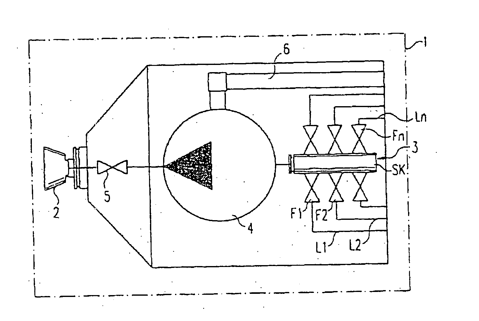
[0012] The valveless
piston pump described in DE 102 13 270 (EP 1 348 487), the entire contents of which are incorporated herein by reference, is preferably used here as the
metering pump, whose
piston is rotated at each piston
stroke around its axis, which runs in the direction of the
stroke and which distinguishes itself due to many fundamental advantages. Among these advantages are the very small
dead volume of the pump, resulting in correspondingly lower paint and purging agent losses when changing colors, fast and effective purging of the
pump head resulting in
high productivity and process reliability when
coating work pieces and great precision in metering (<0.2%) without pulsation and dynamic problems. In addition to these characteristics, the low weight and small size of the pump are of primary importance, so that it also fits into small atomizers, such as are desirable for painting robots when
coating confined and hard-to-access work piece areas including interiors and with good dynamic properties. In addition, this pump manages with small and light drives because of its low torque requirement, while on the other hand it makes high transfer pressure possible, which can be needed for many high-
viscosity coating materials for example. The pump has the additional
advantage of simple and low-intensity maintenance design with few
moving parts, in particular only one piston in the flow area easily manufactured with minimal tolerance. Even giving up these advantages, the invention can be implemented with other known volumetric metering pumps, for example, with a
gear pump constructed as small as possible.
[0025] To reduce the space required for the color changer and its normally pneumatic control lines, the further possibility exists of furnishing as valves for the color change valve arrangement in the way known from EP 1 205 256 pneumatic valves piloted by a
solenoid valve or by other type of electric valve, which communicate or can communicate with an
electronic control system through an array of electrical connections contained in the valve arrangement. In this, pneumatic valves are interposed in the central passage of the color changer and are opened and closed by pressurized air or another pressurized gas from a common pressurized gas line leading through the color changer to all valves. Inside the color changer a
solenoid valve is interposed in the pressurized gas passage for the
pneumatic valve. A data
bus for
digital control data can lead through the color changer linked to the solenoid valves by an
electronic circuit. The previously required numerous control air hoses for the color changer are no longer needed.

