Window sill flashing

Inactive Publication Date: 2005-02-17
PN II
View PDF29 Cites 24 Cited by
  • Summary
  • Abstract
  • Description
  • Claims
  • Application Information

AI Technical Summary

Problems solved by technology

The bottom portion of the window opening (called the sill) is susceptible to rotting if water is not prevented from penetrating from around the window perimeter.
Additionally, adjacent ceilings, plastered walls, and the like are suscepti

Method used


Image

  • Window sill flashing
  • Window sill flashing
  • Window sill flashing

Examples


Embodiment Construction

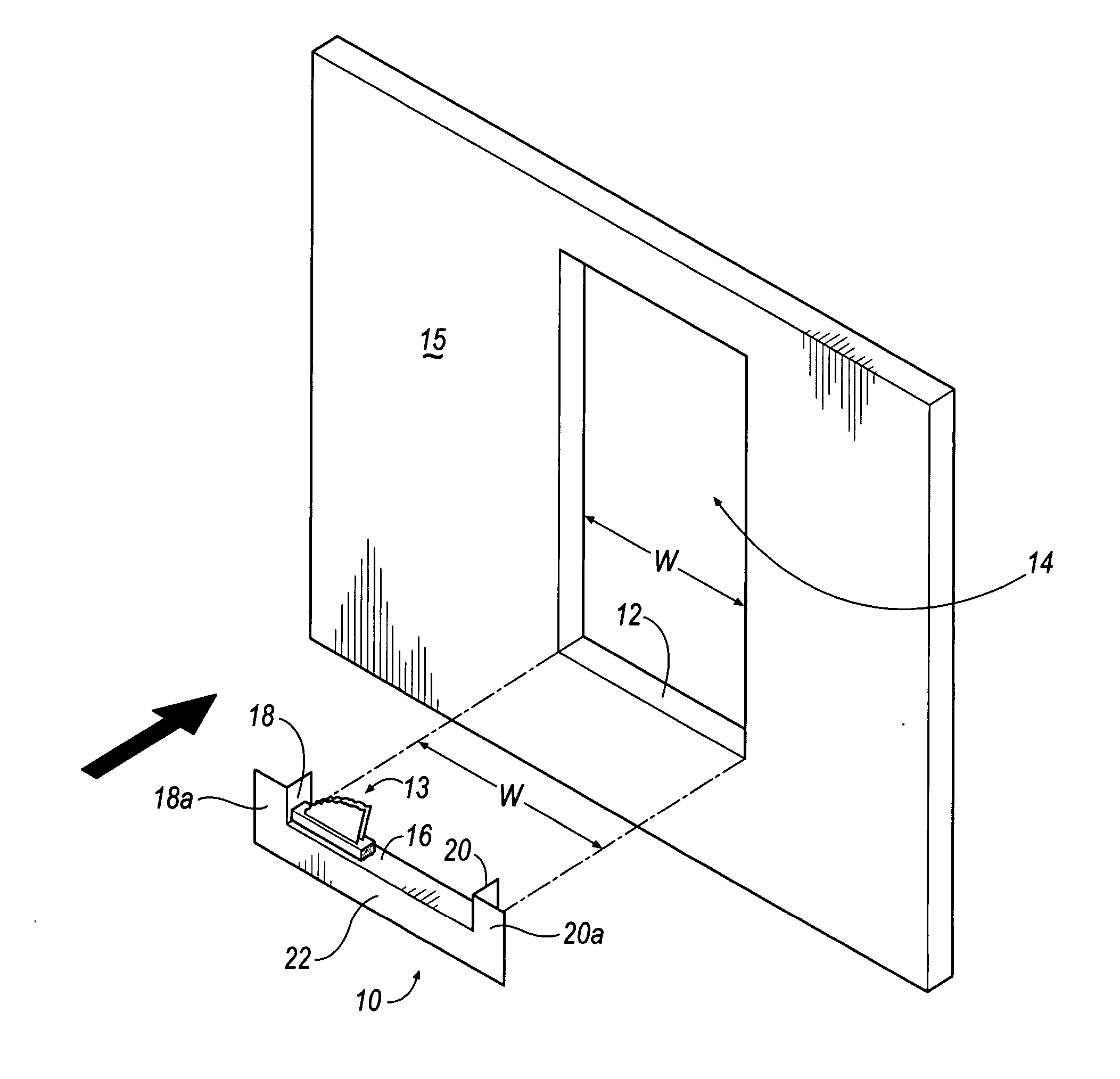
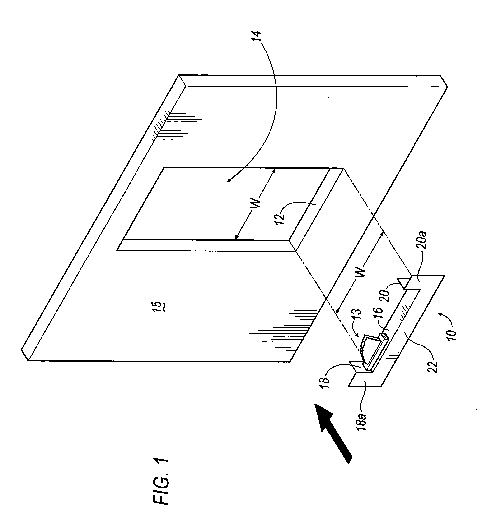
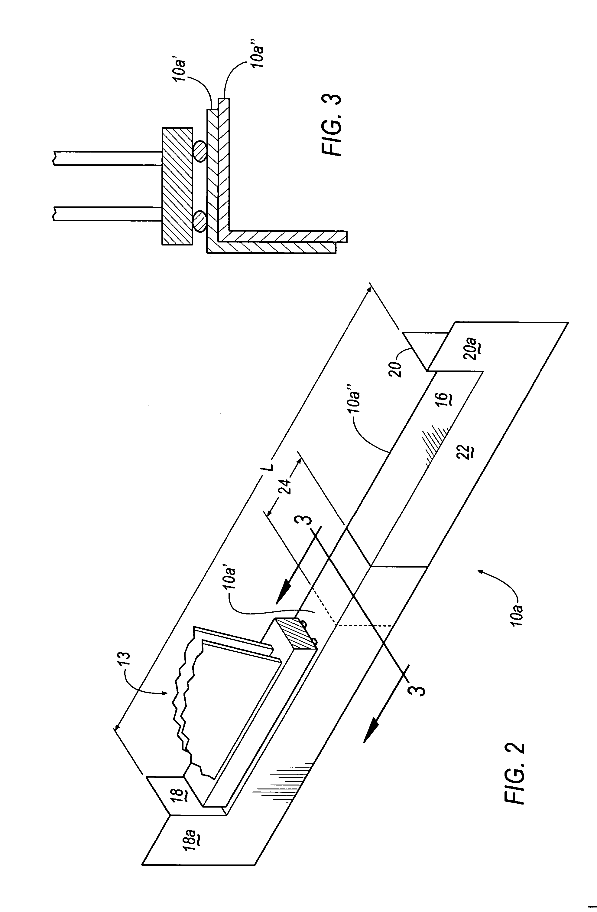
Referring to FIG. 1, a window sill flashing (hereinafter referred to as “flashing”) 10 is generally shown according to an embodiment of the present invention. The flashing 10 is formed to fit within and snugly conform to a bottom portion 12 of a window opening 14 of a wall 15. Window opening 14 has a width W and is adapted to accept a window assembly 13. As illustrated, the face portion (or flange) 22 of flashing 10 is generally U-shaped and constructed as one piece. The flashing 10 comprises a base 16, a first side flange 18 integrally formed with base 16 at one end, a second side flange 20 integrally formed with base 16 at an opposite end, and a front flange 22 integrally formed with base 16. Preferably base 16, side flanges 18, 20 and front flange 22 are all vacuum formed from a common sheet. Front (U-shaped) flange 22 extends perpendicularly downward from an edge of base 16. First side flange 18 includes a front surface 18a and second side flange 20 includes a front surface 20a...


PUM

PropertyMeasurementUnit
Lengthaaaaaaaaaa
Lengthaaaaaaaaaa
Shapeaaaaaaaaaa

Abstract

The present invention is directed towards a window sill flashing comprising a base having a substantially rectangular shape. A front flange projects perpendicularly downward from a front edge of the base and at least one side flange extends vertically from a side edge of the base. The side flange includes a front surface. The window sill flashing is made from a rigid homopolymer vinyl film.

Description

TECHNICAL FIELD The present invention generally relates to building materials and more particularly relates to window sill flashing for a window frame to prevent the ingress of water. BACKGROUND OF THE INVENTION Typical wall construction techniques include forming a rough opening from framing members such that a window opening is formed. The bottom portion of the window opening (called the sill) is susceptible to rotting if water is not prevented from penetrating from around the window perimeter. Additionally, adjacent ceilings, plastered walls, and the like are susceptible to damage if rain-water infiltrates under the window sill. Many systems are used to solve the problem of water intrusion. One method includes providing a means to collect and control the water that does infiltrate the window perimeter. Alternatively, surface sealing agents, such as caulk, expanding foam, and the like are used as filling agents to fill openings between the periphery of the window and the adjace...

Claims


Application Information

Patent Timeline
IPC IPC(8): E06B1/62E06B1/70
CPCE06B1/62E06B1/70E06B7/26E04B1/665B29C67/0011E06B1/702E06B3/66E06B2001/628
Inventor BROAD, ROBERT PATRICKMCDONALD, JAY K.
Owner PN II
Why Eureka
Try Eureka