Gun sight compensator

a compensator and gun sight technology, applied in the field of gun sight compensators, can solve the problems of only producing “windows” of displacement, affecting the lateral displacement of projectiles, and complicating any control,

Inactive Publication Date: 2005-02-24
UNIVERSITY OF WATERLOO
View PDF10 Cites 58 Cited by
  • Summary
  • Abstract
  • Description
  • Claims
  • Application Information

AI Technical Summary

Problems solved by technology

In addition, there are several forces that potentially affect the lateral displacement of a projectile relative to the firing direction, primarily windage (especially crosswinds) and any oblique aiming posture or “canting”.
This greatly complicates any control.
Further, the prism can only produce displacement “windows” within the confines of the image that is available.

Method used


Image

  • Gun sight compensator
  • Gun sight compensator
  • Gun sight compensator

Examples


Embodiment Construction

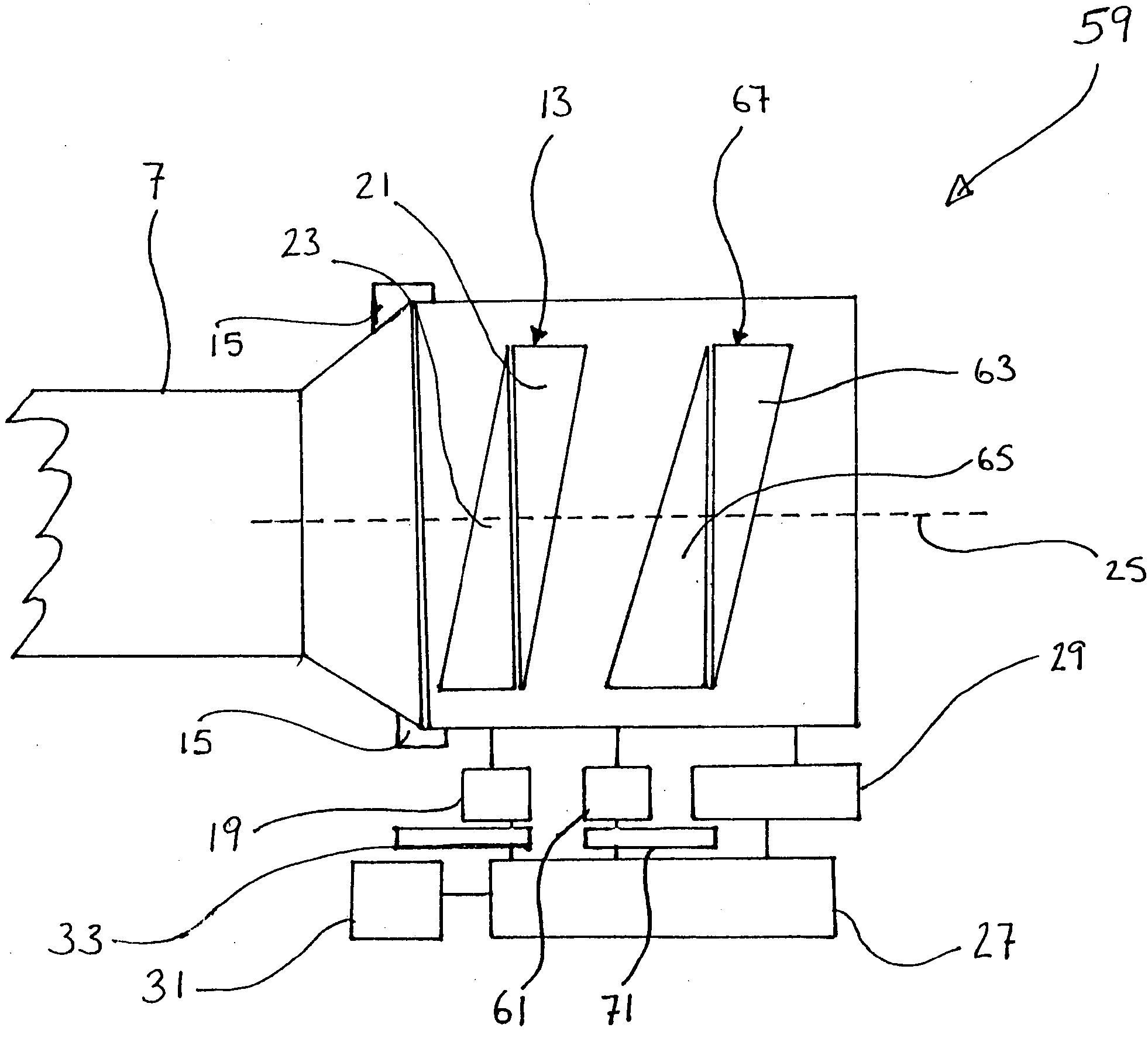
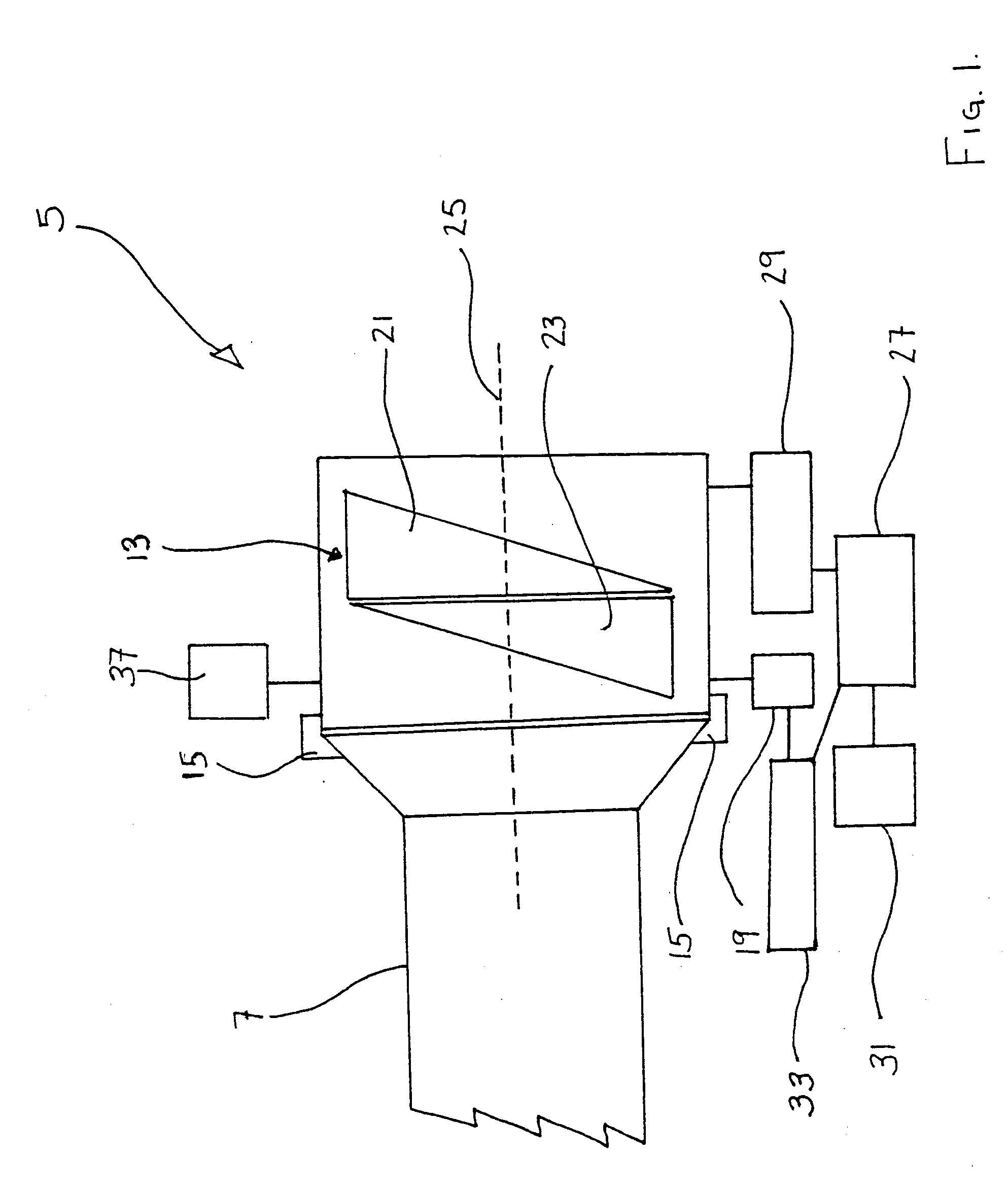
[0029]FIG. 1 illustrates an apparatus generally indicated by reference 5 in accordance with a first embodiment of the present invention. Referring to FIGS. 1 and 3, the apparatus 5 is a range compensator for a gun sight 7, which enables the gun sight 7 to appear “on target” when an associated gun 9 is deviated from a path of light or “line of sight”17 orientation with a target 11 to a “line of departure”35 orientation to compensate for the trajectory characteristics of a projectile to be launched from the gun 9. The “line of departure”35 is the line along which the gun is aligned and defines the initial path of the projectile as it “departs” from the gun. It corresponds to the initial part of the trajectory path 34 which is the path followed by the projectile. The compensator 5 creates an accurate trajectory compensated field of view aligned with the target 11, which allows a point of impact, such as the target 11 to be viewed as the projectile is fired from the gun 9.

[0030] The ex...


PUM


Abstract

A range compensator for a gun sight for an associated gun is provided. The compensator includes at least one Risley prism pair that is rotatable in opposite relative directions about a common axis; mounting means for mounting the Risley prism pair to the sight between the sight and a target at a distance; and, a respective rotator associated with the Risley prism pair for rotating each prism in the Risley prism pair about the axis that is generally aligned with the path. The prisms are rotatable between an unrefracted range finding position in which a “line of departure” required to ensure the projectile strikes the target is determined and a refracted firing position in which the path of light extending between the sight and the target is refractively deviated to maintain the target centered with the sight when the gun is positioned along the required “line of departure”.

Description

FIELD OF THE INVENTION [0001] The present invention relates to a gun sight compensator. BACKGROUND OF THE INVENTION [0002] The trajectory for any projectile, except for self-propelled ones, follows a repeatable pattern when all variables are held constant. Rather than following a flat trajectory, all projectiles drop downwards due to the effects of gravity. The downward displacement at various distances (i.e., the amount of drop) depends largely on the ballistics of the projectile. Other forces influencing the drop dynamics include temperature, humidity, altitude, windage, and angle of fire. In addition, there are several forces that potentially affect the lateral displacement of a projectile relative to the firing direction, primarily windage (especially crosswinds) and any oblique aiming posture or “canting”. [0003] The aggregate impact of all these factors is that the actual projectile flight path deviates in an estimable manner (magnitude and direction) from a straight line of s...

Claims


Application Information

Patent Timeline
Patent Type & Authority Applications(United States)
IPC IPC(8): F41G1/473G02B23/14G02B26/08
CPCF41G1/473G02B26/0883G02B23/14
Inventor STRONG, GRAHAM
Owner UNIVERSITY OF WATERLOO
Why Eureka
Try Eureka