

Locking apparatus with double locking units
a technology of locking unit and locking device, which is applied in the direction of padlocks, building locks, construction, etc., can solve the problems of user loss, trouble and inconvenience for users
- Summary
- Abstract
- Description
- Claims
- Application Information
AI Technical Summary
Problems solved by technology
Method used
Image

Examples
first embodiment
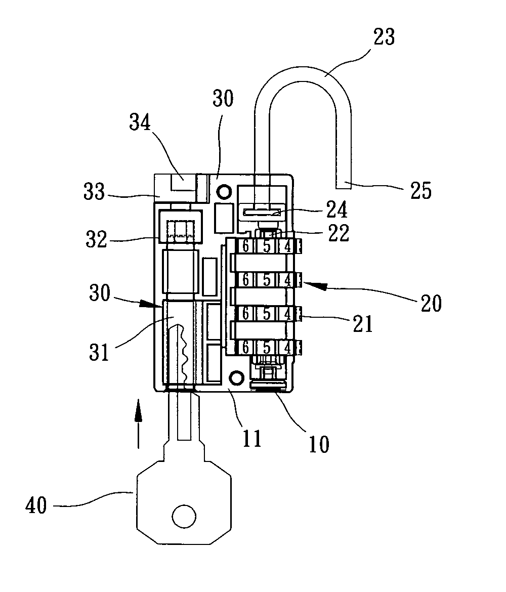
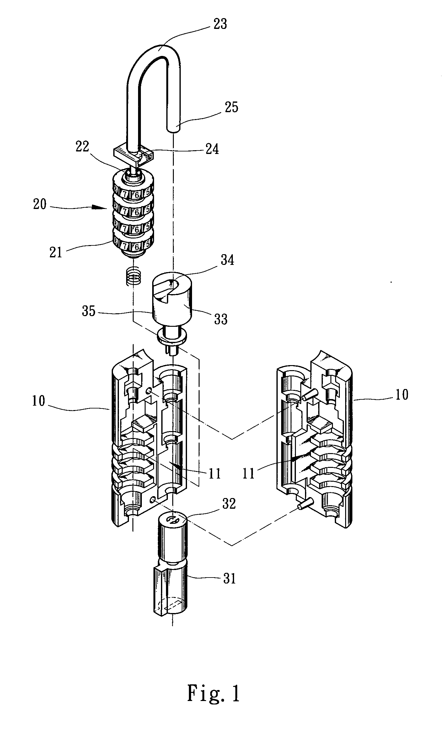
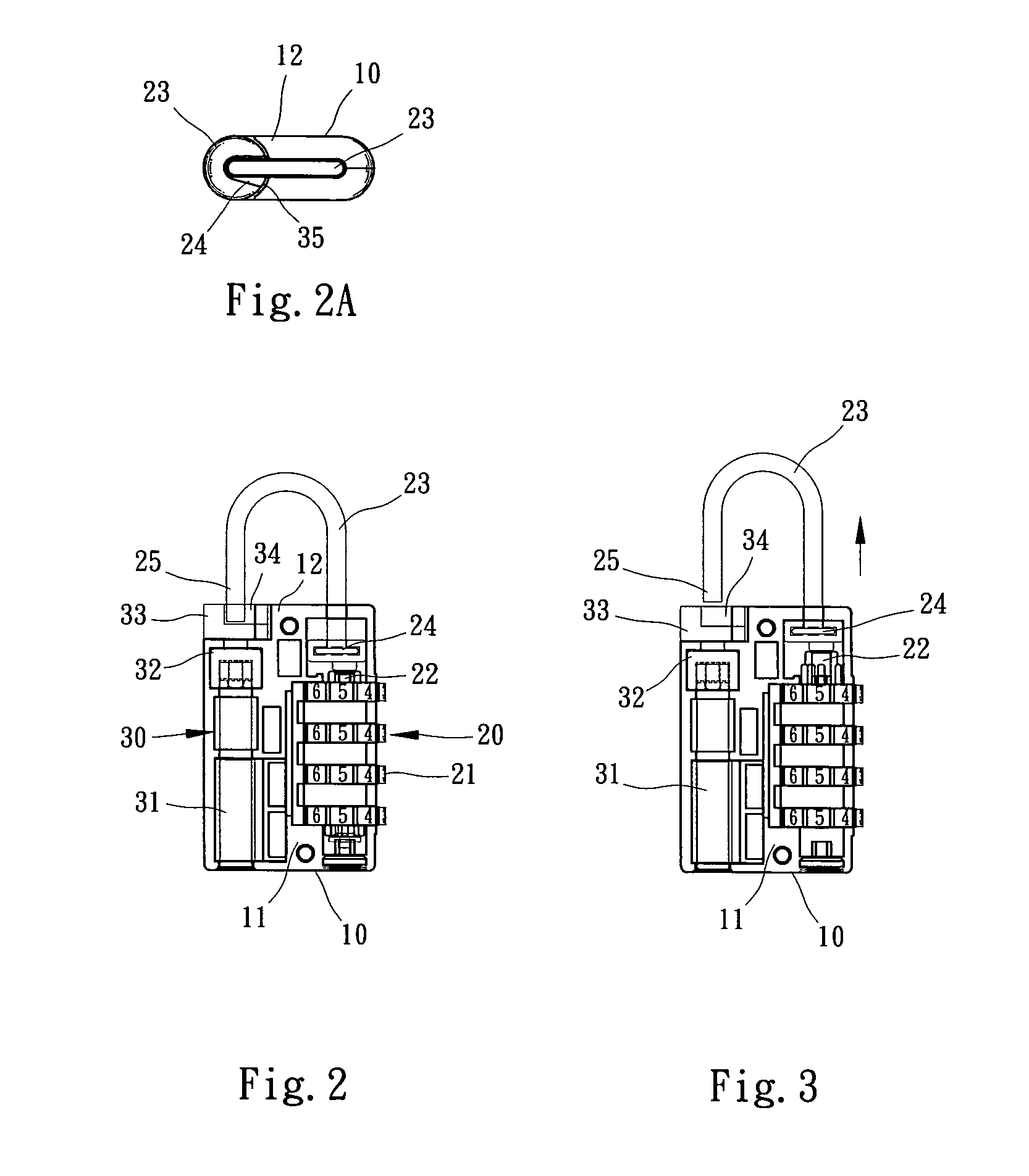
[0028] In the present invention as shown in FIGS. 1 and 2, the controlling unit 30 includes a rotary section 31. A key 40 can be inserted into the rotary section 31 to drive and rotate the rotary section 31. A reactor 32 is mounted on upper side of the rotary section 31 and connected with a driven unit 33. The driven unit 33 outward protrudes from the housing 10. The reactor 32 and the driven unit 33 are rotatable along with the rotary section 31. The driven unit 33 is formed with a notch 34 having an opening 35. The free end 25 of the lock hook or rod member 23 is coaxially detained in the notch 34. FIG. 2A shows that the opening 35 faces the fixed end 24 of the lock hook or rod member 23 and blocked by a ridge section 12 of the housing 10. Under such circumstance, the free end 25 of the lock hook or rod member 23 cannot leave the notch 34. Alternatively, the opening 35 can be directed in reverse to the direction as shown in FIG. 2A to achieve the same effect.
[0029] Referring to FI...
second embodiment
[0032]FIGS. 5 and 5A show the present invention, in which the structure of the controlling unit is modified and denoted by reference numeral 50. The controlling unit 50 includes a rotary section 51 in which a key 40 can be inserted. A head end of the rotary section 51 has a curved slope or a male spiral section 55. A reactor 52 is mounted on upper side of the rotary section 51 and connected with a driven unit 53. The driven unit 53 outward protrudes from the housing 10. The driven unit 53 is formed with a notch 54. The free end 25 of the lock hook or rod member 23 is coaxially detained in the notch 54. In this embodiment, the reactor 52 has a curved slope or female spiral section 56 formed inside the reactor 52. At least a part of the curved slope or female spiral section 56 contacts with or engages with the curved slope or male spiral section 55 of the rotary section 51.
[0033]FIG. 6 shows that when the numeral wheels 21 are turned to a set number, the lock core 22 is permitted to a...
third embodiment
[0035]FIG. 8 shows the present invention, in which the structure of the controlling unit is modified and denoted by reference numeral 60. The controlling unit 60 includes a rotary section 61 in which a key 40 can be inserted. A head end of the rotary section 61 has a switch 65. In this embodiment, the switch 65 is a semicylindrical body as shown in FIG. 8A. A reactor 62 is mounted on upper side of the rotary section 61 and connected with a driven unit 63. The driven unit 63 is formed with a dent 64 having an opening. The opening of the dent 64 faces the fixed end 24 of the lock hook or rod member 23. The driven unit 63 and the ridge section 12 of the housing 10 together detain the free end 25 of the lock hook or rod member 23 as shown in FIG. 8B.
[0036] The lower end of the reactor 62 is formed with a key 66 corresponding to the switch 65 of the rotary section. The reactor 62 has a spring 67 which always exerts an outward swinging force onto the driven unit 63 disposed on the reactor...
PUM
 Abstract
Description
Claims
Application Information