
Dual container system and method of manufacturing the same

a container system and container technology, applied in the direction of rigid containers, transportation and packaging, other domestic objects, etc., can solve the problems of inability to withstand repeated or repetitive impacts originating from the environment, detract from the overall utility of the system, and the dual container system of the conventional art is frequently subject to tear and/or rupture, so as to increase the flow of preform materials to selected portions of the expandable molding balloon

Inactive Publication Date: 2005-02-24
LOWANCE PHILIP D
View PDF24 Cites 0 Cited by
  • Summary
  • Abstract
  • Description
  • Claims
  • Application Information

AI Technical Summary

Benefits of technology

"The present invention is an improved dual container system that can withstand impacts and is designed to prevent leaks and slippage. The system includes a first container and a second container, with the second container having a thicker body and a larger volume than the first container. The second container has a body recess that engages with the first container and a supporting shelf to hold the first container in place. The second container also has a handle and lateral body extensions that capture the first container. The invention provides a more stable and reliable container system for various products."

Problems solved by technology

Although the current dual container systems may achieve their primary objective of product user-friendliness, they possess certain deficiencies which detract from their overall utility.
Perhaps the greatest deficiency of the conventional dual container systems is the inability to withstand repeated or repetitive impacts originating from their environment.
The dual container systems of the conventional art are frequently subjected to tear and / or rupture as many of them are repeatedly dropped and / or mishandled during their shipment and / or storage.
In particular, the recess of the larger container which is used for engaging the smaller container is vulnerable to tear and / or rupture as its edges forming the outer boundaries thereof are not sufficiently thickened.
Even more vulnerable than the recess edges are the corners formed on the bottom portion the recess.
More particularly, these bottom corners of the recess are extremely thin compared to the other portions of the larger container.
This is understood to be a result of manufacturing deficiency in which insufficient amounts of preform materials are distributed to that region.
As such, while the rest of the larger container is uniformly thickened to a sufficient degree, it is often the case that the bottom corners of its recess fail to reach the same, or even similar, thickness.
In this regard, the bottom recess corners are especially prone to being torn or ruptured.
Obviously, this has the inevitable negative effect of spilling or discharging some, if not all, of the products contained within the larger container.
The product loss resulting from such structural failure may become burdensome when translated into dollars and cents in loss profits.
Another significant deficiency that casts a shadow upon the dual container systems of the conventional art is the inability of the larger container to provide an adequate horizontal support for the smaller container.
However, those mechanisms cannot account for certain situations such as the smaller container being inadvertently slipped out through the underside of the recess due to the force of gravity.
This scenario is more likely to happen as the time goes on since the mechanisms for engaging the smaller container would eventually become weakened.
As such, the risk of container slippage is a possibility which can detrimentally undermine the overall utility and value of the dual container system.

Method used


Image

  • Dual container system and method of manufacturing the same
  • Dual container system and method of manufacturing the same
  • Dual container system and method of manufacturing the same

Examples


Embodiment Construction

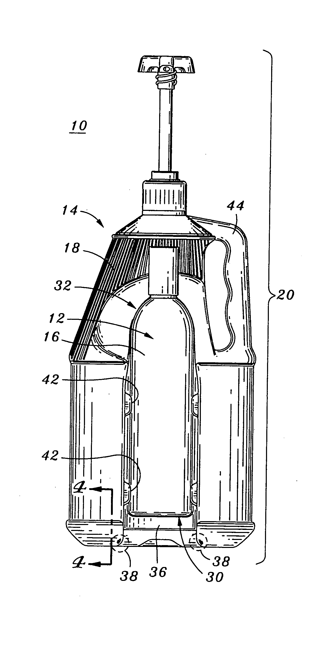
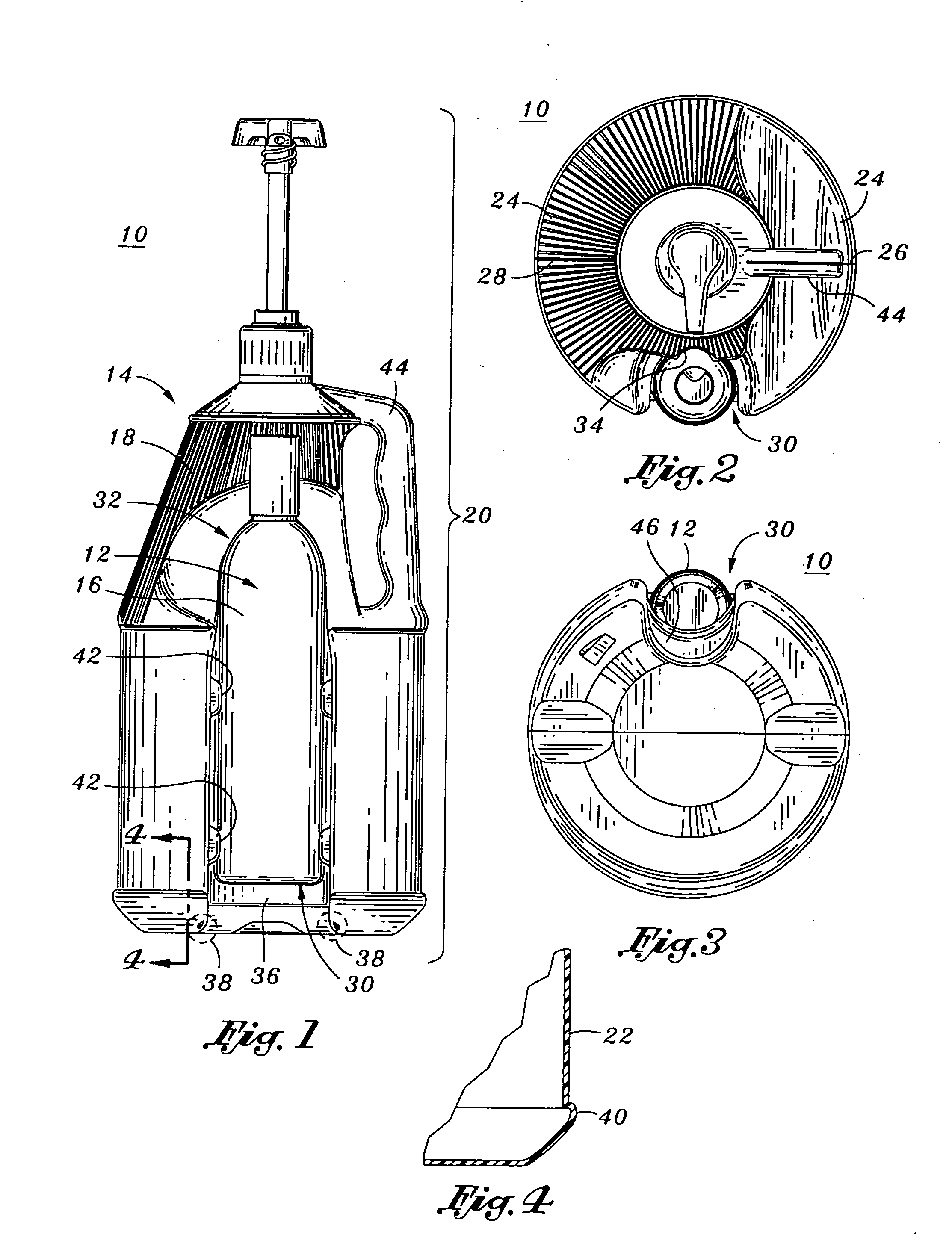
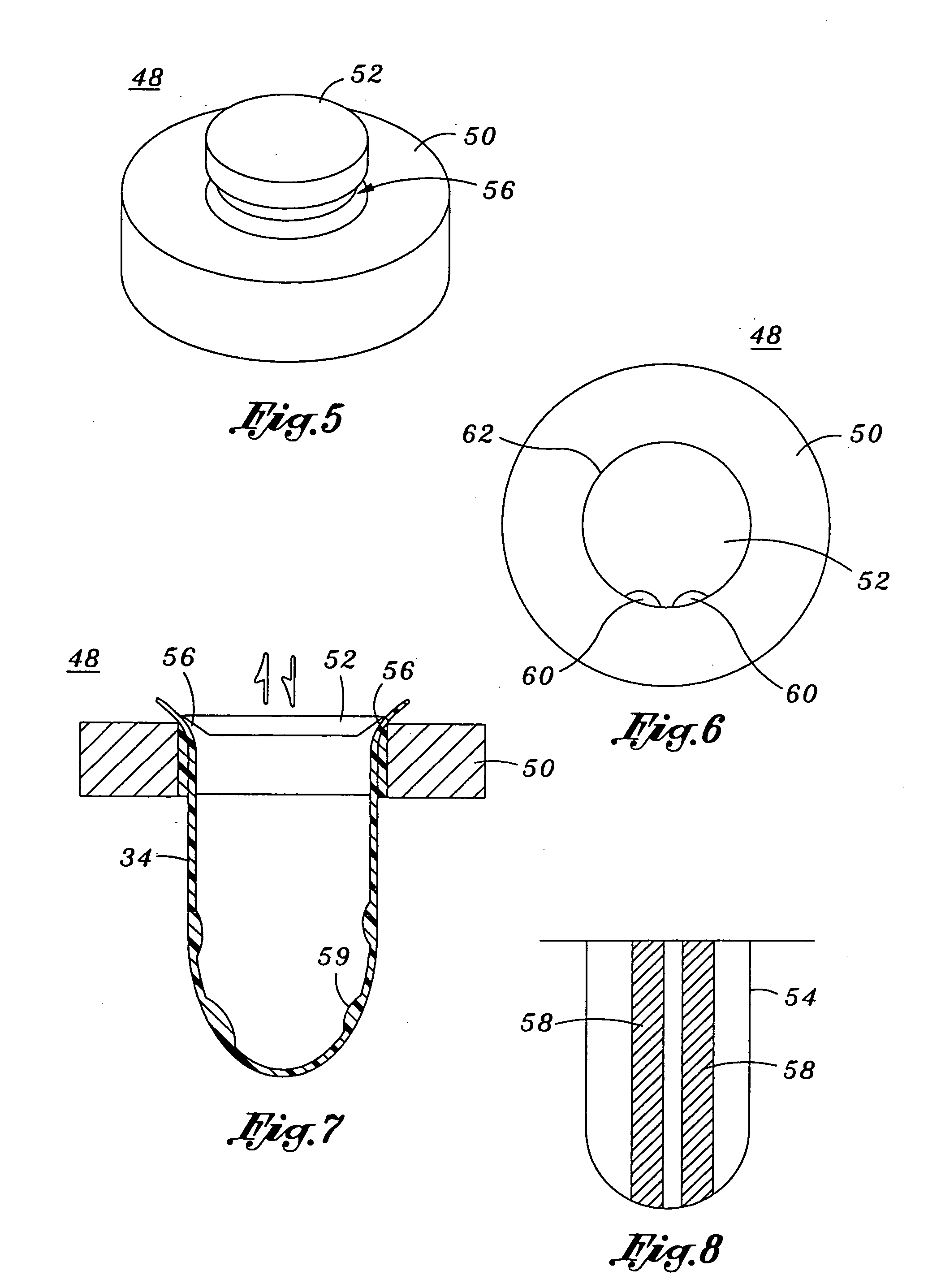
[0040] Referring now to the drawings wherein the showings are for purposes of illustrating preferred embodiments of the present invention only, and not for purposes of limiting the same, FIG. 1 illustrates a dual container system 10 constructed in accordance with a preferred embodiment of the present invention. Similar to its prior art counterparts, the dual container system 10 of the present invention is configured to offer the convenience and freedom of product mobility by providing an overall system in which a first container 12 (i.e. smaller container) can be engaged and disengaged from a second container 14 (i.e., larger container). However, unlike its prior art counterparts, the present dual container system 10 possesses one uniform wall thickness throughout the entirety of its body so as to be impact-resistant and further provides a unique horizontal support for accommodating the first container 12 when it engages the second container 14. These features will be better explain...


PUM

PropertyMeasurementUnit
thicknessaaaaaaaaaa
thicknessaaaaaaaaaa
thicknessesaaaaaaaaaa

Abstract

There is provided a container system adapted to withstand a single impact or repeated impacts. The container system features a first container having a first container body. The container system further features a second container which has a second container body. The second container defines a second body height and a second body wall thickness. A body recess which is adapted to releasibly engage the first container body of the first container is formed on the second container body and is extended along the second body height. The body recess defines at least one recess bottom corner having a recess bottom corner wall thickness which is at least identical to the second body wall thickness of the second container body. This specified bottom corner wall thickness of the body recess allows the second container to withstand the single impact or repeated impacts.

Description

CROSS-REFERENCE TO RELATED APPLICATIONS [0001] (Not Applicable) STATEMENT RE: FEDERALLY SPONSORED RESEARCH / DEVELOPMENT [0002] (Not Applicable) BACKGROUND OF THE INVENTION [0003] The present invention relates generally to dual container systems, and more particularly to an improved dual container system featuring an impact-resistant container which possesses one uniform wall thickness throughout the entirety of its body and provides a unique horizontal support for its counterpart container that engages therewith. [0004] It is a common practice for manufacturers and / or retailers to employ the use of containers for packaging their products and making them available in the marketplace. These containers not only protect the products from contamination, but may further facilitate the use of the products. Indeed, the significance and importance of providing user-friendly containers are truly appreciated by various industries as they can increase the overall attractiveness and appeal of the...

Claims


Application Information

Patent Timeline
Patent Type & Authority Applications(United States)
IPC IPC(8): B29C49/00B29C49/04B29C51/02B29C51/26B65D21/02
CPCB29B2911/1402B29B2911/14026B29B2911/14033B29B2911/1404B29C49/0073B29B2911/1438B29C51/02B29C51/261B29L2031/463B65D21/0237B29B2911/14326B29C49/04B29C2949/26B29C2949/28B29C2949/24B29C2949/22B29C2949/0725B29C2949/072B29C2949/0724B29C2949/0764B29C49/071B29C2949/0721
Inventor LOWANCE, PHILIP D.
Owner LOWANCE PHILIP D
Learn More