Hot melt adhesive detection methods

a detection method and adhesive technology, applied in the field of hot melt adhesive systems, can solve problems such as the limitation of the area that may be monitored by the sensor

Inactive Publication Date: 2005-02-24
ILLINOIS TOOL WORKS INC
View PDF27 Cites 18 Cited by
  • Summary
  • Abstract
  • Description
  • Claims
  • Application Information

AI Technical Summary

Problems solved by technology

In order to precisely detect the beginnings and ends of adhesive beads and other thermal materials, the sensor must be equipped with...

Method used


Image

  • Hot melt adhesive detection methods
  • Hot melt adhesive detection methods
  • Hot melt adhesive detection methods

Examples


Embodiment Construction

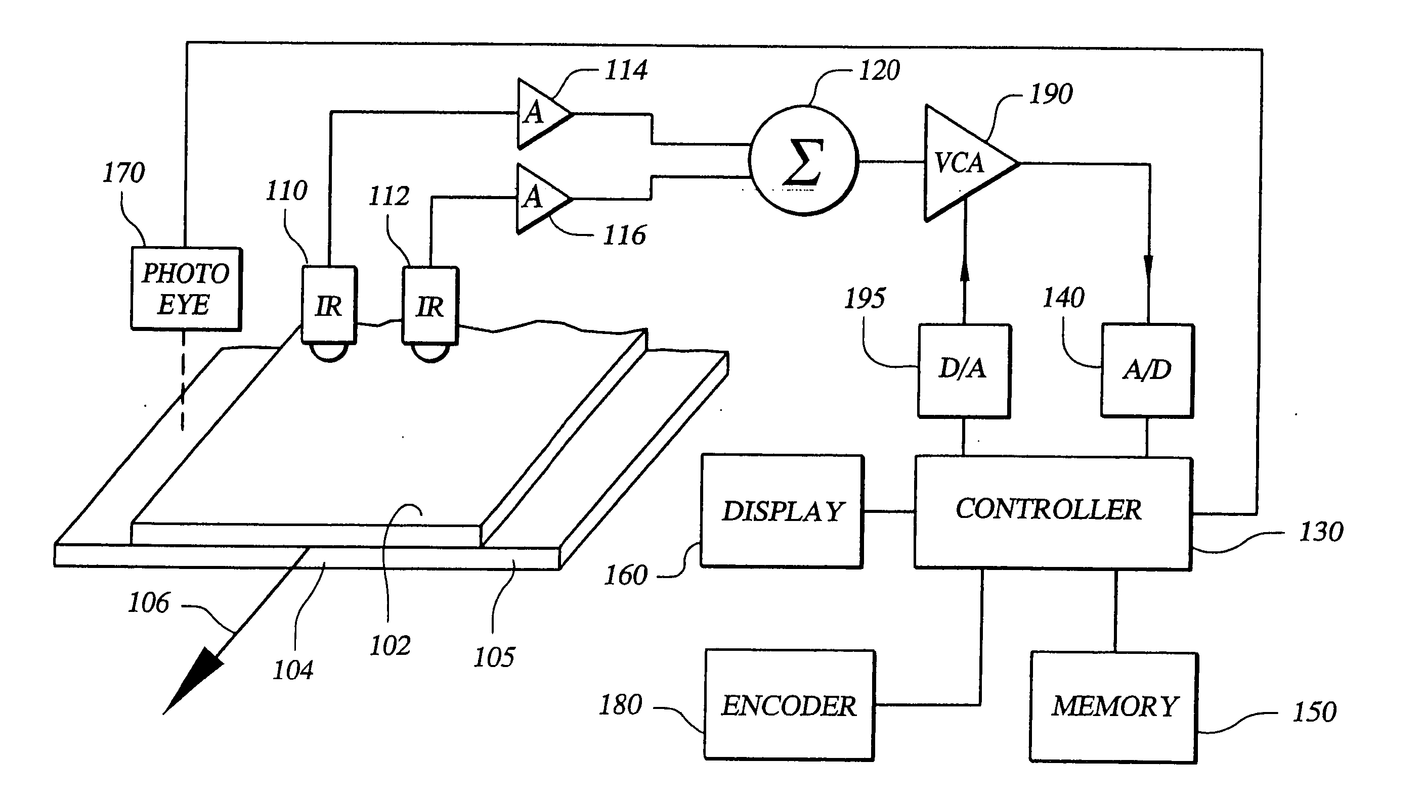
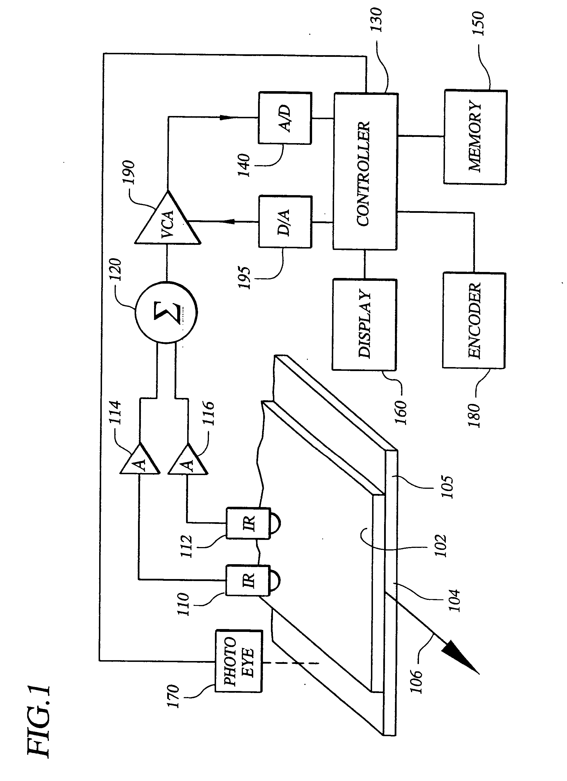
[0029]FIG. 1 is an exemplary thermal sensing system 100 for detecting target articles, or targets, at temperatures different than ambient temperature, for example, a hot melt adhesive 102 deposited onto a moving substrate or packaging 104 as illustrated in FIG. 1. In other applications, the thermal sensing systems of the present inventions are useful for detecting other substances, other than hot melt adhesives. These and other applications will become more fully apparent to those having ordinary skill in art upon consideration of the exemplary embodiments below.

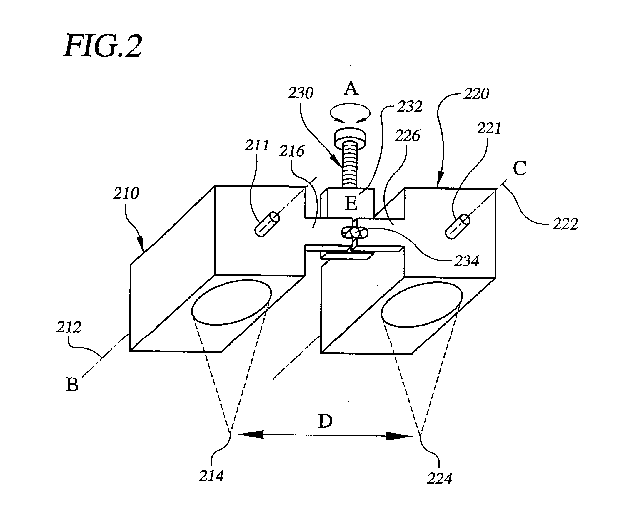
[0030] In one embodiment of the invention, the thermal sensing system comprises generally a plurality of at least two thermal sensors mounted in or on a mounting member, for example, a mounting member positionable relative to the target to be detected by the detectors. The plurality of sensors are preferably oriented non-parallel to a direction of relative motion between the sensors and the target. These and other aspects o...


PUM

PropertyMeasurementUnit
Temperatureaaaaaaaaaa
Threshold limitaaaaaaaaaa

Abstract

A hot melt adhesive sensing system and methods including detecting (410) multiple areas of a target, for example a hot adhesive material, by sensing changes in temperature with a corresponding number of thermal sensors, summing (420) an output of the thermal sensors, and evaluating (430) the summed output by comparing the summed output with a variable reference, the results of which may be assessed relative to a specified tolerance.

Description

CROSS-REFERENCE TO RELATED APPLICATIONS [0001] The present application is a division of U.S. application Ser. No. 10 / 356,771 filed on 1 Feb. 2003, which is a continuation-in-part of co-pending U. S. Application No. 10 / 254,316 filed on 25 Sep. 2002 and entitled “Hot Melt Adhesive Detection Methods And Systems”, both of which are assigned commonly with the instant application and incorporated by reference herein, and from which benefits are hereby claimed under 35 U.S.C. § 120.BACKGROUND OF THE DISCLOSURE [0002] The disclosure relates generally to hot melt adhesive systems, and more particularly to the application and detection of hot materials, for example, hot melt adhesives deposited on substrates, methods and systems therefor. [0003] The non-contact detection of beads of hot adhesives on moving conveyors by using infrared sensors that detect temperature differences between the adhesive and the substrate is known generally. [0004] U.S. Pat. No. 4,831,258 entitled “Dual Sensor Radia...

Claims


Application Information

Patent Timeline
IPC IPC(8): G01J5/00
CPCG01J5/0022
Inventor HEERDT, DIETER B.JENKINS, PAUL M.
Owner ILLINOIS TOOL WORKS INC
Why Eureka
Try Eureka