Folding knife with lock mechanism

Inactive Publication Date: 2005-03-03
GERBER SAKAI
View PDF12 Cites 56 Cited by
  • Summary
  • Abstract
  • Description
  • Claims
  • Application Information

AI Technical Summary

Benefits of technology

[0004] It is an objective of the present invention to provide

Problems solved by technology

However, there are very few locking mechanis

Method used


Image

  • Folding knife with lock mechanism
  • Folding knife with lock mechanism
  • Folding knife with lock mechanism

Examples


Embodiment Construction

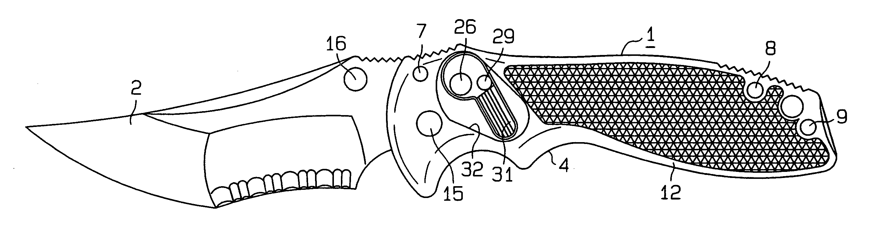
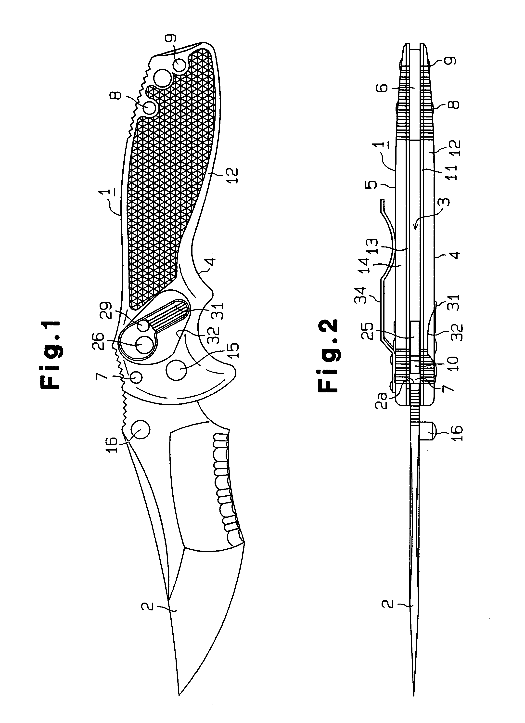
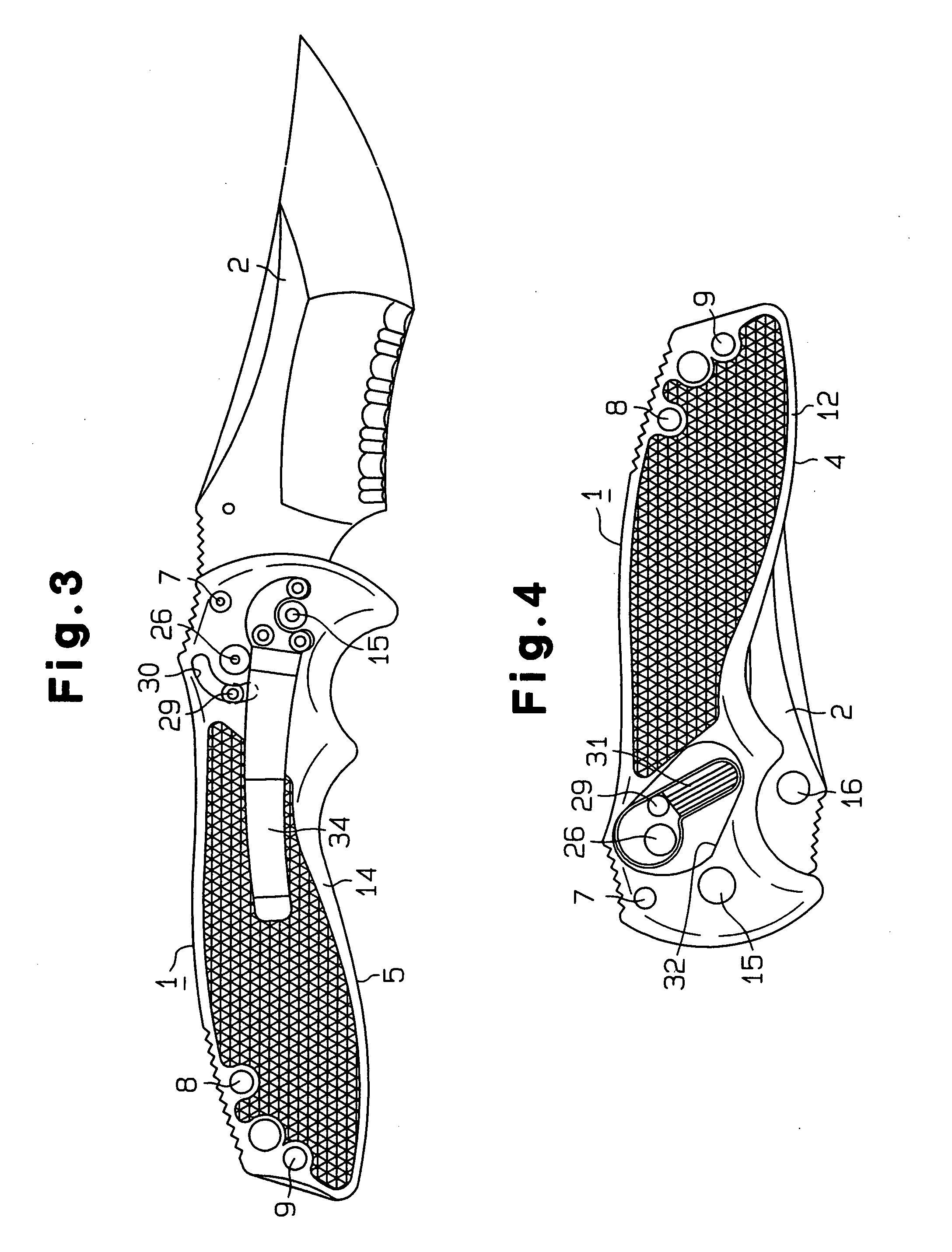
[0014] One embodiment of the present invention will be described with reference to FIGS. 1-10. As shown in FIGS. 1-6, the folding knife includes a handle 1 and a blade 2, which is pivotally attached to the distal end portion of the handle 1. The blade 2 is movable between a retracted storage position (see FIGS. 4-6) where the blade 2 is stored in a storage 3 of the handle 1 and an open extended position (see FIGS. 1-3, 5) where the blade 2 is exposed and extends from the handle 1. The retracted storage position corresponds to a resting position for the blade 2, and the open extended position corresponds to a working position for the blade 2.

[0015] The handle 1 has a first side wall 4, a second side wall 5 and a metallic spacer 6 interposed between them in the vicinity of the proximal end portion of the handle 1. The side walls 4, 5 are connected to each other with the spacer 6 interposed between them by a first connecting pin 7, a second connecting pin 8 and a third connecting pin ...


PUM


Abstract

A folding knife is provided with a handle and a blade which is pivotally supported by the handle through a blade shaft. The blade has a tang provided with a cam surface. The cam surface contains a substantially arcuate guide portion and an engage portion formed contiguous to one end of the guide portion. A lock plate is rotatably supported by the handle. The lock plate is rotatable between a lock position where it is engaged with the engage portion and an unlock position where it is disengaged from the engage portion. When the blade is located at an open extended position, a torsion spring rotates the lock plate so as to lock the blade against the handle. Thus, the blade is securely locked at the open extended position.

Description

BACKGROUND OF THE INVENTION [0001] The present invention relates to a folding knife that has a locking mechanism for locking a blade at an open extended position. [0002] A conventional folding knife includes a handle and a blade, which is pivotally supported at the distal end portion of the handle. A shaft is mounted in the distal end portion of the handle and extends perpendicular to the blade. The tang of the blade is pivotally supported by the shaft. The blade is movable between a retracted storage position (resting position) where the blade is retracted into a recess of the handle and an open extended position (working position) where the blade is exposed and extends from the handle. [0003] The folding knife is also provided with a locking mechanism for locking the blade at the open extended position. Various types of locking mechanisms for that purpose have conventionally been proposed and are put into practical uses. A locking mechanism should fulfill various conditions, e.g.,...

Claims


Application Information

Patent Timeline
IPC IPC(8): B26B1/04
CPCB26B1/04
Inventor NISHIHARA, TOMIO
Owner GERBER SAKAI
Why Eureka
Try Eureka