Lock mechanism

a technology of locking mechanism and locking mechanism, which is applied in the direction of padlocks, building locks, constructions, etc., can solve the problems of locking and becoming inseparabl

Inactive Publication Date: 2005-03-03
SINOX CO LTD
View PDF15 Cites 54 Cited by
  • Summary
  • Abstract
  • Description
  • Claims
  • Application Information

AI Technical Summary

Problems solved by technology

Once coupled, it may be loc

Method used


Image

  • Lock mechanism
  • Lock mechanism
  • Lock mechanism

Examples


second embodiment

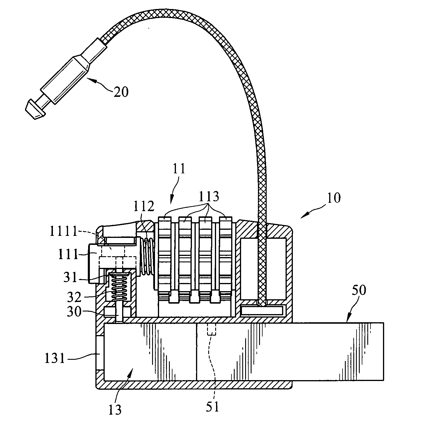
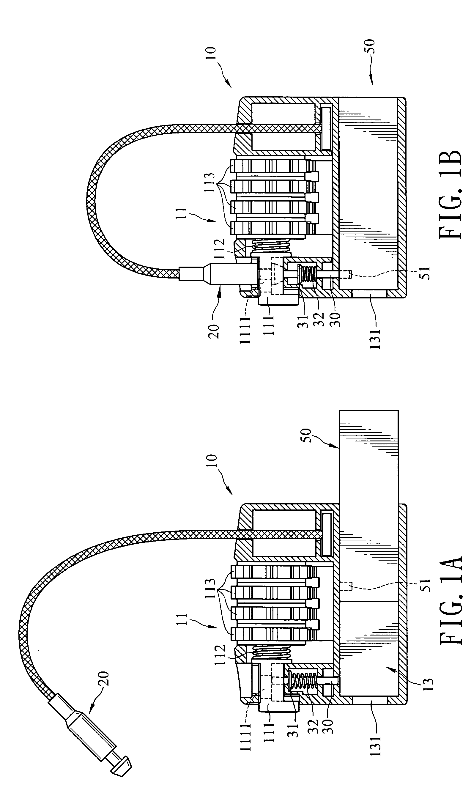
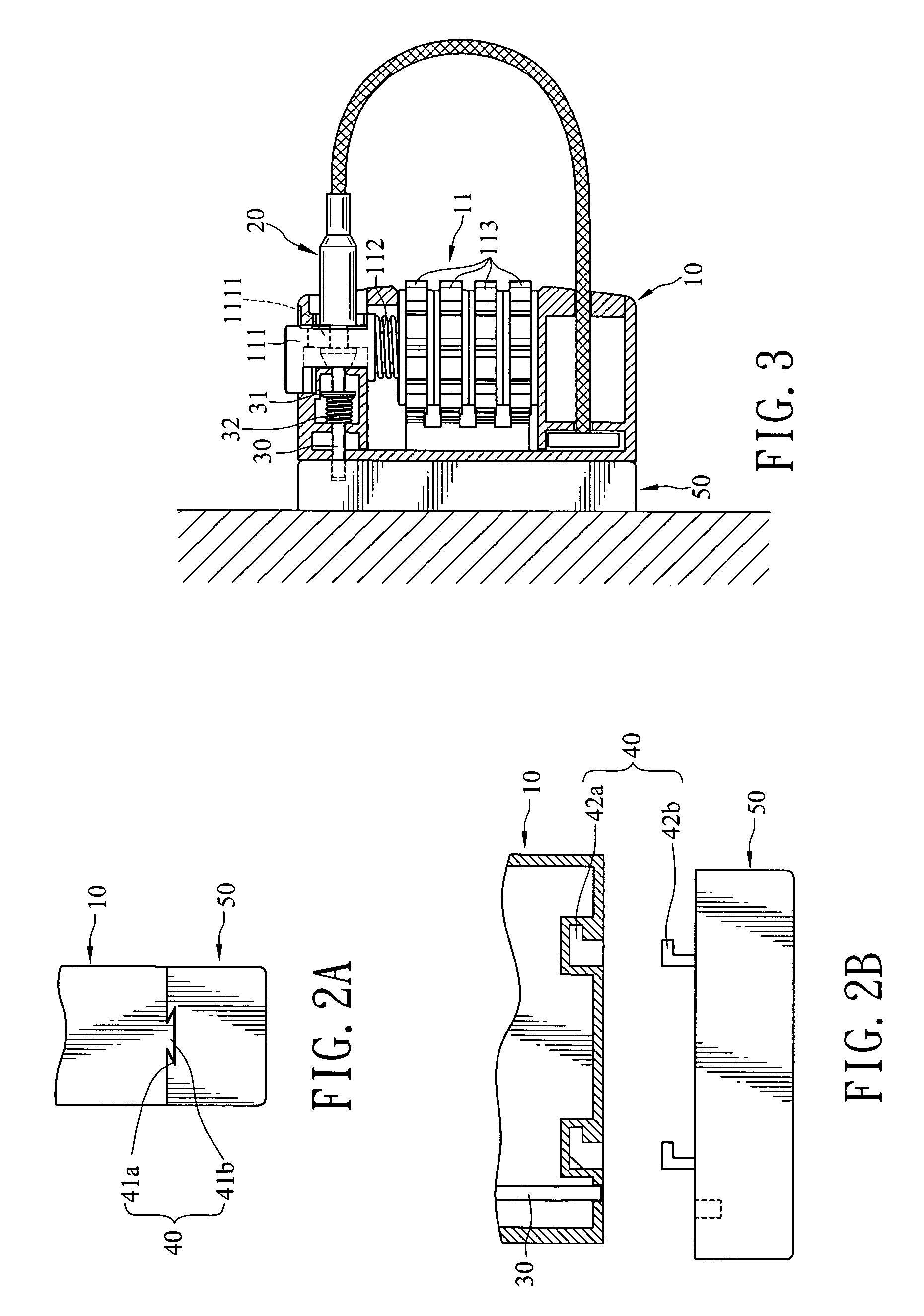
[0025] Refer to FIG. 2 for the invention. It also has a second shackle 30 driven by a first shackle 20. The first shackle 20 latches a first object, and the second shackle 30 latches a second object 50. For the first shackle 20 made of a flexible wire, the case 10 houses a winch 12 which includes a rotary wheel 121, a brake member 122 and an actuating member 123. The first shackle 20 has one end fastened to the rotary wheel 121, and may be wound on the winch through the rotary wheel 121. The rotary wheel 121 has a plurality of ratchet teeth 1211 on the peripheral rim. The brake member 122 can be engaged with the ratchet teeth 1211 to provide a brake function, and is driven by the actuating member 123 so that the brake member 122 may be moved to latch the ratchet teeth 1211 and prevent the rotary wheel 121 from rotating, or be moved away from the ratchet teeth 1211 so that the rotary wheel 121 may rotate as desired.

[0026] Referring to FIGS. 6A, 6B and 6C, the actuating member 123, as...

fourth embodiment

[0031] Refer to FIG. 8 for the invention. In this embodiment, the actuating member 60 of the previous embodiment is replaced by an actuating member 123 of the winch 12. The actuating member 123 has a guiding slot 1231 to drive the second shackle 30 to change position.

[0032] Referring to FIG. 9, the actuating member 123 set forth above may also be linked to the second shackle 30 through at least one linkage bar 1431 so that the second shackle 30 may be driven to change position by the actuating member 123 through the linkage bar 1431. Furthermore, the linking condition between the actuating member 123 and the second shackle 30 may also adopt that shown in FIG. 10. The actuating member 123 and the second shackle 30 have mating wedge sections 1432 and 33 that have sloped surfaces to achieve the desired linkage movement.

[0033] Refer to FIG. 11 for yet another embodiment of the invention. In this embodiment, the actuating member60 of the previous embodiment is replaced by the movable st...


PUM


Abstract

A lock mechanism for latching a first object then coupling with a second object includes a case, a first shackle and a second shackle. The case includes a bolt assembly. The first shackle may be selectively coupled with the case to form a closed boundary with the case and latch the first object at a latch position, and unfasten the closed boundary at a release position. At the latch position, the first shackle is latched and anchored by the bolt assembly. The second shackle is movably mounted on the case and may latch the second object at a first position and release the second object at a second position.

Description

FIELD OF THE INVENTION [0001] The invention relates to a lock mechanism for latching an object or coupling one object with another object to form a latched and inseparable connection. BACKGROUND OF THE INVENTION [0002] A padlock for latching a guarded object is a product to protect the object from being stolen. Aiming at different guarding objects and functionality, many dedicated lock products have been developed, such as door locks, safe locks, bicycle locks, ski locks, and the like. [0003] In the lock applications, there are also locks that have a built-in chamber such as those disclosed in U.S. Pat. Nos. 1,955,809, 4,838,052, 5,267,460 and 5,737,947. Depending on different usages, the chamber can contain required articles (such as keys, small tools, etc.). The lock has a lid that may be opened or closed and latched to keep the articles safely inside. [0004] However, the chamber provided in those types of locks usually has a fixed housing compartment. The size and shape of the co...

Claims


Application Information

Patent Timeline
IPC IPC(8): E05B37/02E05B67/00E05B67/02E05B73/00
CPCE05B37/025E05B73/0005E05B67/02E05B67/003Y10T70/435Y10T70/424
Inventor LING, RENNY TSE-HAWWU, CHUN-SHENGWU, CHENG-HORNG
Owner SINOX CO LTD
Why Eureka
Try Eureka