Gravel packing a well

a well and groove technology, applied in the direction of sealing/packing, wellbore/well accessories, drilling pipes, etc., can solve the problems of high viscosity fluid, high cost of high-viscosity fluid, and premature exit of fluid from slurry

Inactive Publication Date: 2005-03-03
SCHLUMBERGER TECH CORP
View PDF51 Cites 25 Cited by
  • Summary
  • Abstract
  • Description
  • Claims
  • Application Information

AI Technical Summary

Problems solved by technology

A potential challenge with a conventional gravel packing operation deals with the possibly that fluid may prematurely leave the slurry.
Thus, the bridge disrupts and possibly prevents the application of gravel around some parts of the sandscreen.
However, the high viscosity fluid typically is expensive and may present environmental challenges relating to its use.
However, a potential challenge in using the low viscosity fluid is that the velocity of the slurry must be higher than the velocity of the high viscosity fluid-based slurry in order to prevent fluid from prematurely leaving the slurry.

Method used


Image

  • Gravel packing a well
  • Gravel packing a well
  • Gravel packing a well

Examples


Embodiment Construction

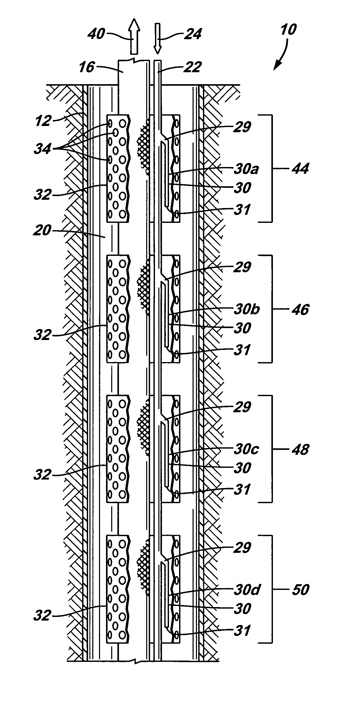
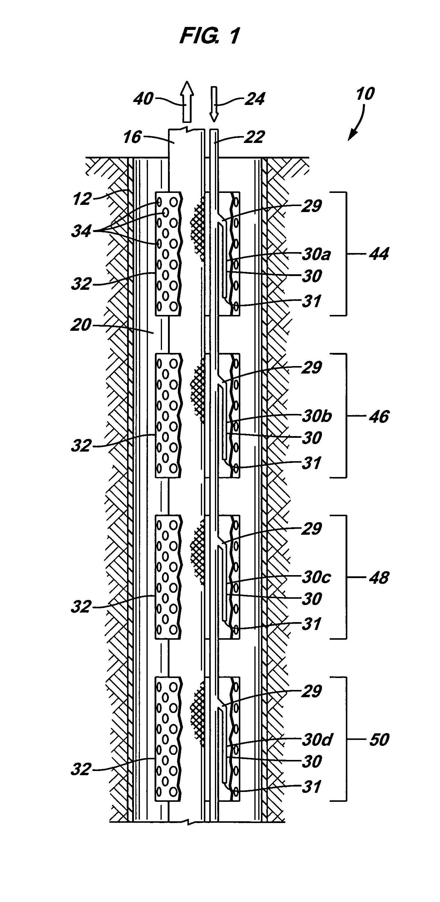
[0021] Referring to FIG. 1, an embodiment 10 of a gravel packing system in accordance with the invention includes a generally cylindrical sandscreen 16 that is inserted into a wellbore of a subterranean well. The sandscreen 16 is constructed to receive well fluid through its sidewall from one or more subterranean formations of the well. As shown in FIG. 1, the sandscreen 16 may be located inside a well casing 12 of the well. An annulus 20 is formed between the interior surface of the well casing 12 and the components of the system 10. It is noted that in some embodiments of the invention, the well may be uncased well, and thus, in these embodiments of the invention, the annulus 20 may be located between the components of the system 10 and the uncased wall of the wellbore.

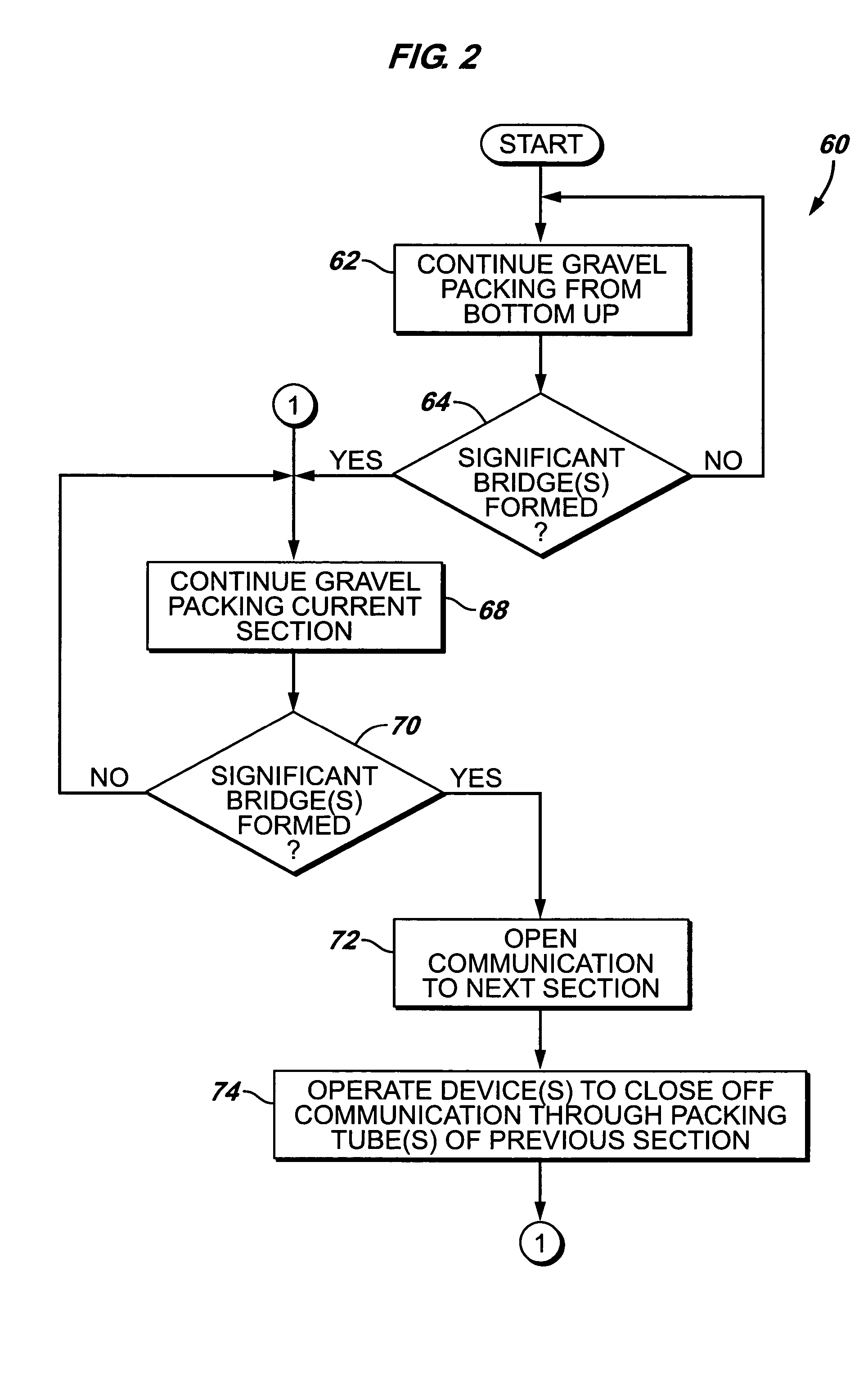
[0022] In accordance with some embodiments of the invention, a two-phase gravel packing operation is used to distribute gravel around the sandscreen 16. The first phase involves gravel packing the well from the bot...


PUM


Abstract

A technique that is usable with a subterranean well includes communicating a slurry through a shunt flow path and operating a control device to isolate slurry from being communicated to an ancillary flow path. The system may include a shunt tube and a diverter. The shunt tube is adapted to communicate a slurry flow within the well to form a gravel pack. The diverter is located in a passageway of the shunt tube to divert at least part of the flow. A slurry may be communicated through the shunt flow path, and a control device may be operated to isolate the slurry from being communicated to the ancillary flow path.

Description

BACKGROUND [0001] The invention generally relates to gravel packing a well. [0002] When well fluid is produced from a subterranean formation, the fluid typically contains particulates, or “sand.” The production of sand from the well must be controlled in order to extend the life of the well. One technique to accomplish this involves routing the well fluid through a downhole filter formed from gravel that surrounds a sandscreen. More specifically, the sandscreen typically is a cylindrical mesh that is inserted into and is generally concentric with the borehole of the well where well fluid is produced. Gravel is packed between the annular area between the formation and the sandscreen, called the “annulus.” The well fluid being produced passes through the gravel, enters the sandscreen and is communicated uphole via tubing that is connected to the sandscreen. [0003] The gravel that surrounds the sandscreen typically is introduced into the well via a gravel packing operation. In a conven...

Claims


Application Information

Patent Timeline
Patent Type & Authority Applications(United States)
IPC IPC(8): E21B17/18E21B34/06E21B43/04
CPCE21B43/045E21B17/18E21B34/063
Inventor WANG, DAVID WEIKHAN, BRUNOLANGLAIS, MICHAEL D.
Owner SCHLUMBERGER TECH CORP
Why Eureka
Try Eureka