Angle-adjustable hinge

a technology of angle adjustment and hinge, which is applied in the direction of beach chairs, movable seats, chairs, etc., can solve the problems of small number of angle change stages, rough pitch of gear teeth, and claw pieces and gear teeth,

Inactive Publication Date: 2005-03-03
YAMASHITA TADANOBU
View PDF5 Cites 24 Cited by
  • Summary
  • Abstract
  • Description
  • Claims
  • Application Information

AI Technical Summary

Problems solved by technology

In the conventional hinge, the claw piece and teeth of the gear are large, and pitch of the teeth of the gear is rough because force working between the first arm and the second arm (force necessary to restrict the oscillation) is to be very larg

Method used


Image

  • Angle-adjustable hinge
  • Angle-adjustable hinge
  • Angle-adjustable hinge

Examples


Embodiment Construction

[0031] Preferred embodiments of the present invention will now be described with reference to the accompanying drawings.

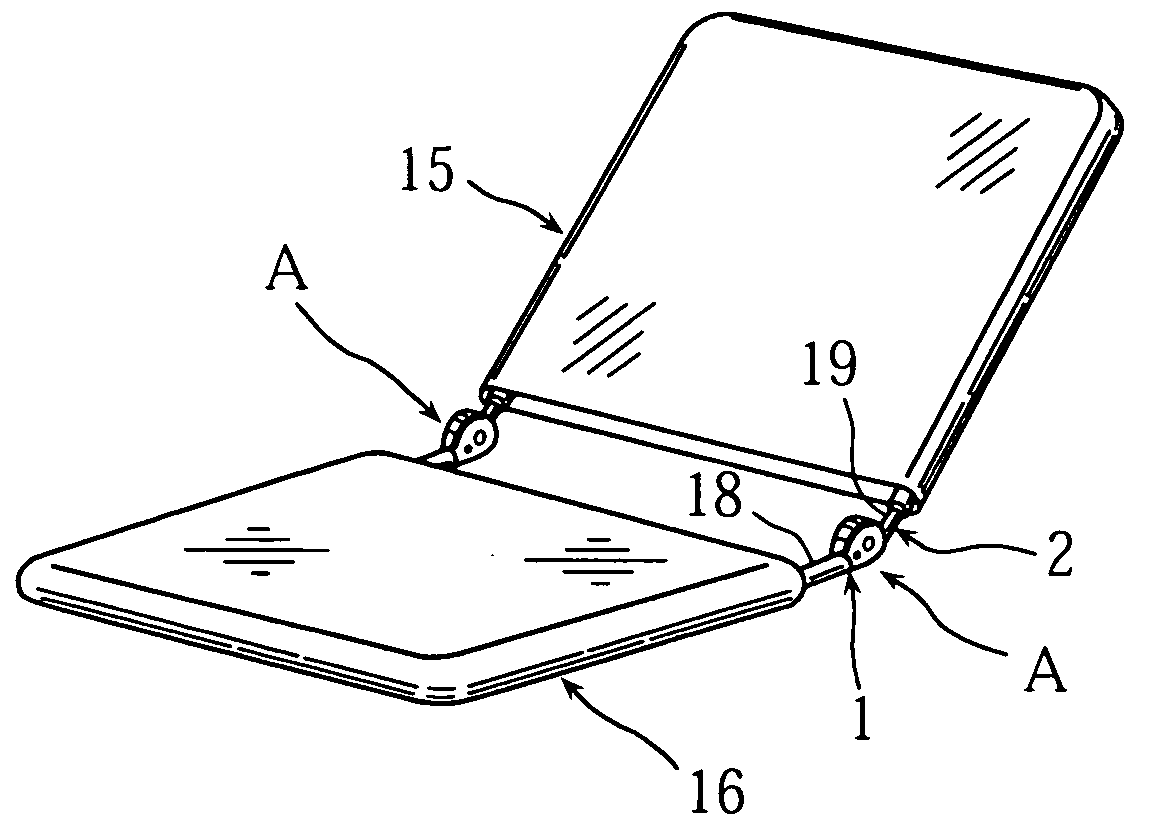
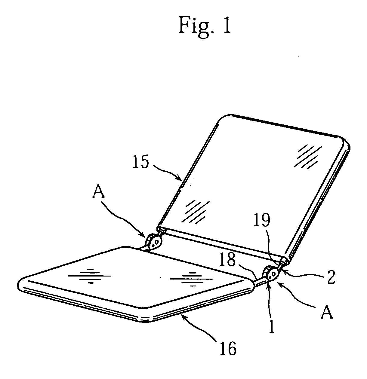
[0032] An angle-adjustable hinge relating to the present invention is, for example, in a legless chair having a back 15 and a seat 16 as shown in a perspective view of FIG. 1, disposed between the back 15 and the seat 16 to adjust inclination angle of the back 15. That is to say, this angle-adjustable hinge A is a joint hinge (connecting hinge) having angle-adjusting function. The hinge A can be used for a sofa, a head rest, a foot rest, etc. other than the legless chair, assembled with two oscillating members, and also used for shelves of which doors are opened and closed by oscillation.

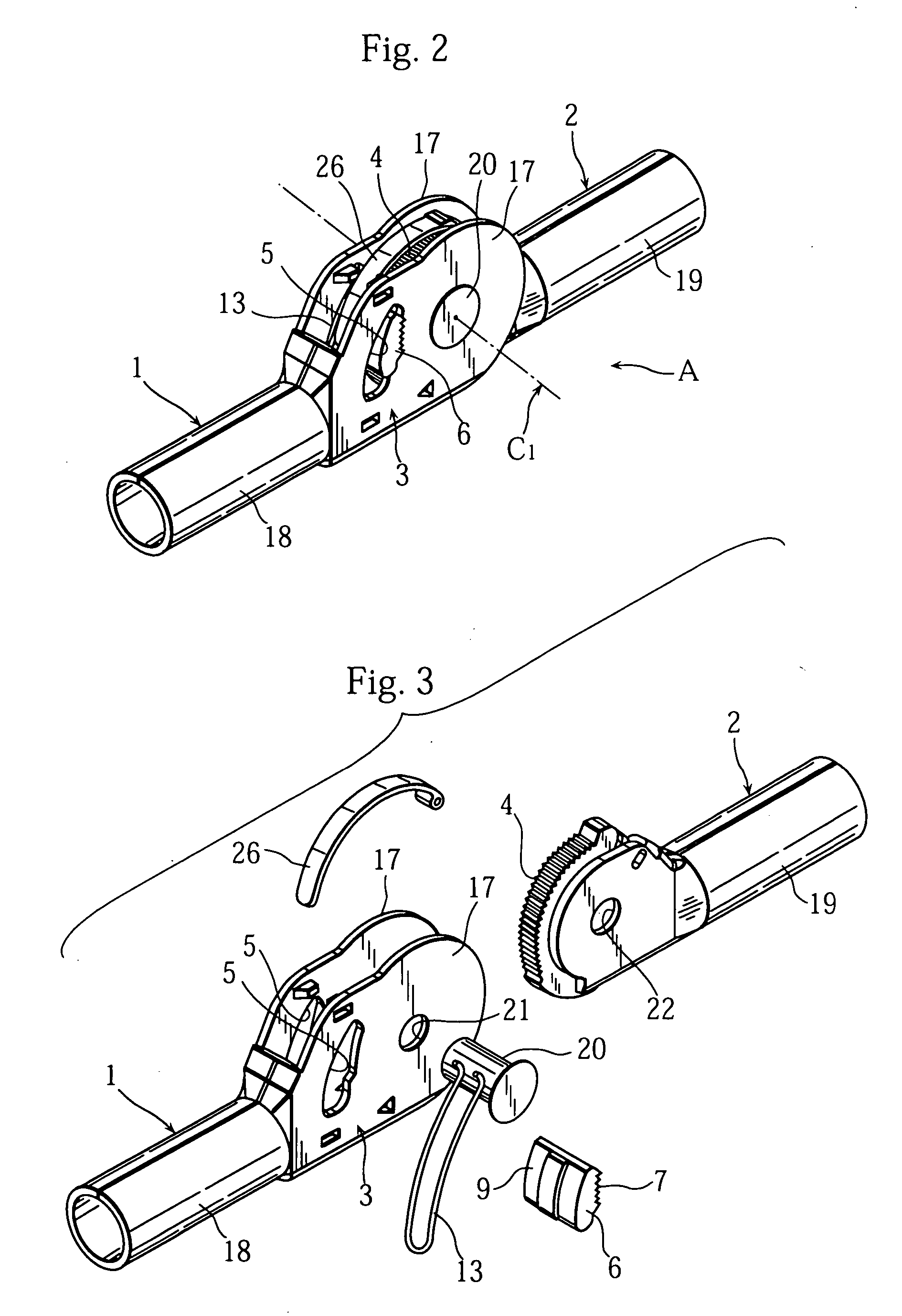
[0033]FIG. 2 is a perspective view of the angle-adjustable hinge A, and FIG. 3 is an exploded perspective view of the same.

[0034] The angle-adjustable hinge A of the present invention is provided with a first arm 1 provided with a case portion 3 and a second arm 2, connected to ...


PUM


Abstract

An angle-adjustable hinge provided with a first arm having a case portion and a second arm connected to the first arm with the case portion as to oscillate around a first axis and having a gear portion. The angle-adjustable hinge is also provided with a wedge-shaped window portion formed on the case portion of the first arm and a floating wedge member, disposed as to move within the wedge-shaped window portion, having one face side as a toothed face to engage with the gear portion and another face side as a contact face to contact a wedge face on an outer side of the wedge-shaped window portion.

Description

BACKGROUND OF THE INVENTION [0001] 1. Field of the Invention [0002] This invention relates to an angle-adjustable hinge as a joint member with which an angle formed by members on one side and another side can be freely set. [0003] 2. Description of the Related Art [0004] A legless chair having a back 15 and a seat 16 as shown in a perspective view of FIG. 1 is provided with a hinge between the back 15 and the seat 16 having angle-adjusting function to adjust an inclination angle of the back 15, namely, an angle-adjustable hinge A. [0005] This conventional hinge is constructed as that a gear and a claw piece of a second arm on another side (the back 15 side) are held in a case portion of a first arm connected to one side (the seat 16 side) to restrict oscillation of the second arm in an extending direction (reclining direction of the back 15) to the first arm by engagement of the claw piece with the gear (refer to Japanese utility model publication No. 59-20118). [0006] In the conven...

Claims


Application Information

Patent Timeline
IPC IPC(8): A47C1/026A47C4/10E05D7/00E05D11/10F16C11/10
CPCA47C1/026A47C3/16E05D7/0009Y10T16/5402E05Y2900/148Y10T16/541E05D11/1007A47C1/146
Inventor YAMASHITA, TADANOBU
Owner YAMASHITA TADANOBU
Why Eureka
Try Eureka