Microsystem with an element which can be deformed by a thermal sensor

a thermal sensor and microsystem technology, applied in microstructured technology, piezoelectric/electrostrictive device manufacture/assembly, variable capacitors, etc., can solve the problems of piezoelectric and magnetostrictive materials, difficult to use with classic micro-machining processes, and inability to obtain just a bimetal

Inactive Publication Date: 2005-03-03
COMMISSARIAT A LENERGIE ATOMIQUE ET AUX ENERGIES ALTERNATIVES
View PDF20 Cites 11 Cited by
  • Summary
  • Abstract
  • Description
  • Claims
  • Application Information

AI Technical Summary

Benefits of technology

The part forming the arch is advantageously obtained by a prior deposit on the aforesaid surface of the substrate of a sacrificial mass to give a definite shape to the aforesaid deformable element once the sacrificial mass has been sacrificed, the sacrificial mass being provided so that, at the end of the process, the aforesaid deformable element naturally has a deflection without stress with respect to the aforesaid surface of the substrate.

Problems solved by technology

The thermal sensors appear to be the most useful because they generally allow for larger deformations then electrostatic sensors whereas magnetic sensors, or those which use piezoelectric and magnetostrictive materials, are generally difficult to use with classic micro-machining processes, particularly, for manufacturing which requires technological compatibility with microelectronics.
This cannot be obtained with just a bimetal however.
In the case of a square membrane, A is 2.298 h. One of the drawbacks of this method is the indeterminate nature of the sign of f. As FIG. 4 shows, the membrane 7 may be deformed in the opposite direction and take the position indicated by the broken line.
Equation (2) also shows that it is difficult to obtain high displacement amplitudes for structures made by surface technologies, i.e. in thin layers.

Method used


Image

  • Microsystem with an element which can be deformed by a thermal sensor
  • Microsystem with an element which can be deformed by a thermal sensor
  • Microsystem with an element which can be deformed by a thermal sensor

Examples


Embodiment Construction

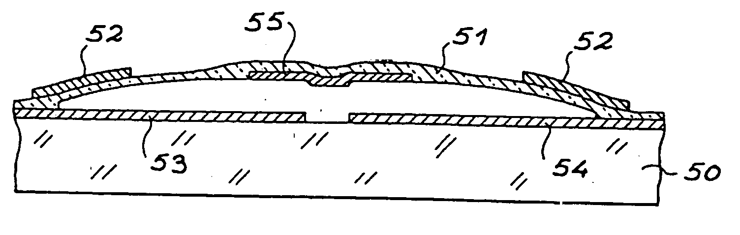
In general, structures obtained by microtechnology processes have planar geometry. Manufacturing of naturally deflected beams or membranes thus requires particular attention.

The processes which will now be described deposit the deformable element on a layer called the sacrificial layer which is then eliminated at the end of the process. A Si3N4 deformable element (beam or membrane) can be made using a sacrificial layer of tungsten.

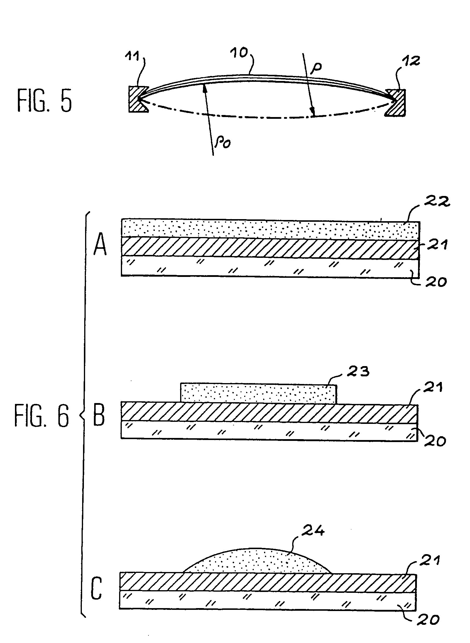
A first variant of the process according to the invention illustrated by FIGS. 6A to 6H yields a microsystem with a deformable element (beam or membrane) which is non-planar and non-forced. On a substrate 20, made of glass for example, the sacrificial layer 21 (made of tungsten for example) is first deposited, then a layer of photosensitive resin 22 (FIG. 6A). The resin layer is etched to leave only a mass of resin 23 of which the area is determined by the desired deformable element (FIG. 6B). By thermal treatment, the flow of the photosensitive resin...


PUM

PropertyMeasurementUnit
temperatureaaaaaaaaaa
stressaaaaaaaaaa
massaaaaaaaaaa

Abstract

The invention involves a microsystem which can be used in particular for making microswitches or microvalves, composed of a substrate (50) and used for shifting between a first state of functioning and a second state of functioning by means of a bimetal-effect thermal sensor. The sensor includes a deformable element (51) attached, at opposite ends, to the substrate (50) so that there is a natural deflection without stress with respect to a surface of the substrate opposite it, this natural deflection determining the first state of functioning, the second state of functioning being caused by the thermal sensor which, under the influence of temperature variation, induces a deformation of the deformable element (51) which diminishes the deflection by subjecting it to a compressive force which shifts it in a direction opposite to its natural deflection by buckling.

Description

FIELD OF THE INVENTION The present invention involves a microsystem with an element which can be deformed by the action of a thermal sensor. Such microsystems can be applied to microswitches for opening or closing electric circuits and microvalves for microfluid applications. These microsystems include an element in the form of a beam or a membrane which is deformed by heat. Strongly non-linear behaviour is sought in order to obtain a rapid shift between the two states, an open state and a closed state. It must be possible to design these microsystems so that they can be compatible with the making of microelectronic components. STATE OF THE ART The microsensors used to trigger the deformation of the deformable element of a microsystem can be put in three main categories as a function of the principles used. First, thermal sensors which use thermal dilatation of one or several of their components. There are also electrostatic sensors which use the electrostatic force generated be...

Claims


Application Information

Patent Timeline
Patent Type & Authority Applications(United States)
IPC IPC(8): H01H1/00
CPCH01H1/0036H01H2001/0042H01H2037/008H01G5/16B81B3/0024B81B2201/016Y10T29/42Y10T29/49124Y10T29/49155Y10T29/49105Y10T29/49128Y10T29/49117B81B2201/032
Inventor FOUILLET, YVES
Owner COMMISSARIAT A LENERGIE ATOMIQUE ET AUX ENERGIES ALTERNATIVES
Why Eureka
Try Eureka