
Decorative modular masonry block

a modular, decorative technology, applied in the field of modular masonry blocks, can solve the problem of limited number of design patterns

Inactive Publication Date: 2005-03-10
BEND INDS
View PDF26 Cites 15 Cited by
  • Summary
  • Abstract
  • Description
  • Claims
  • Application Information

AI Technical Summary

Benefits of technology

"The invention is a modular masonry system that includes units that can be interlocked to create structures with curved surfaces. The units have concave and convex regions that fit together to create a secure connection. The system can be used at angles from 0° to 180° and is adaptable to different needs. The technical effects of the invention include the ability to create curved surfaces with modular masonry units and the creation of a scalloped surface with interlocking units."

Problems solved by technology

Therefore, there are a limited number of design patterns that may be constructed from such units.

Method used


Image

  • Decorative modular masonry block
  • Decorative modular masonry block
  • Decorative modular masonry block

Examples


embodiment

[0064] II. Picket Fence Embodiment

[0065]FIGS. 10-17 illustrate an alternate embodiment of a modular masonry unit 34 configured for use in either a paired block or like-shaped block design. Similar to the modular unit 10 previously described, the modular unit 34 is particularly well-suited for use with a series of essentially identical, like-shaped units 34 to form a garden or flower bed 36, as shown in FIG. 13.

[0066] The unit 34 comprises a central portion 38, a first end portion 40, and a second end portion 42. The unit 34 is preferably of a unitary one-piece construction. The unit 34 has a scalloped top surface 44 defining a series of raised regions or tops 46 that give the unit 34 an aesthetically appealing appearance that mimics a picket-type fence. In the illustrated embodiment, each raised region 46 includes a flat top surface 48 and angled or beveled opposed side surfaces 50. Between adjacent raised regions 46 is an intermediate region 52.

[0067] The unit 34 also includes a ...


PUM


Abstract

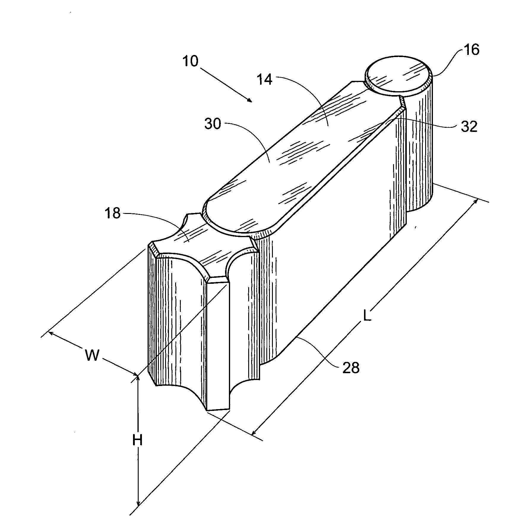
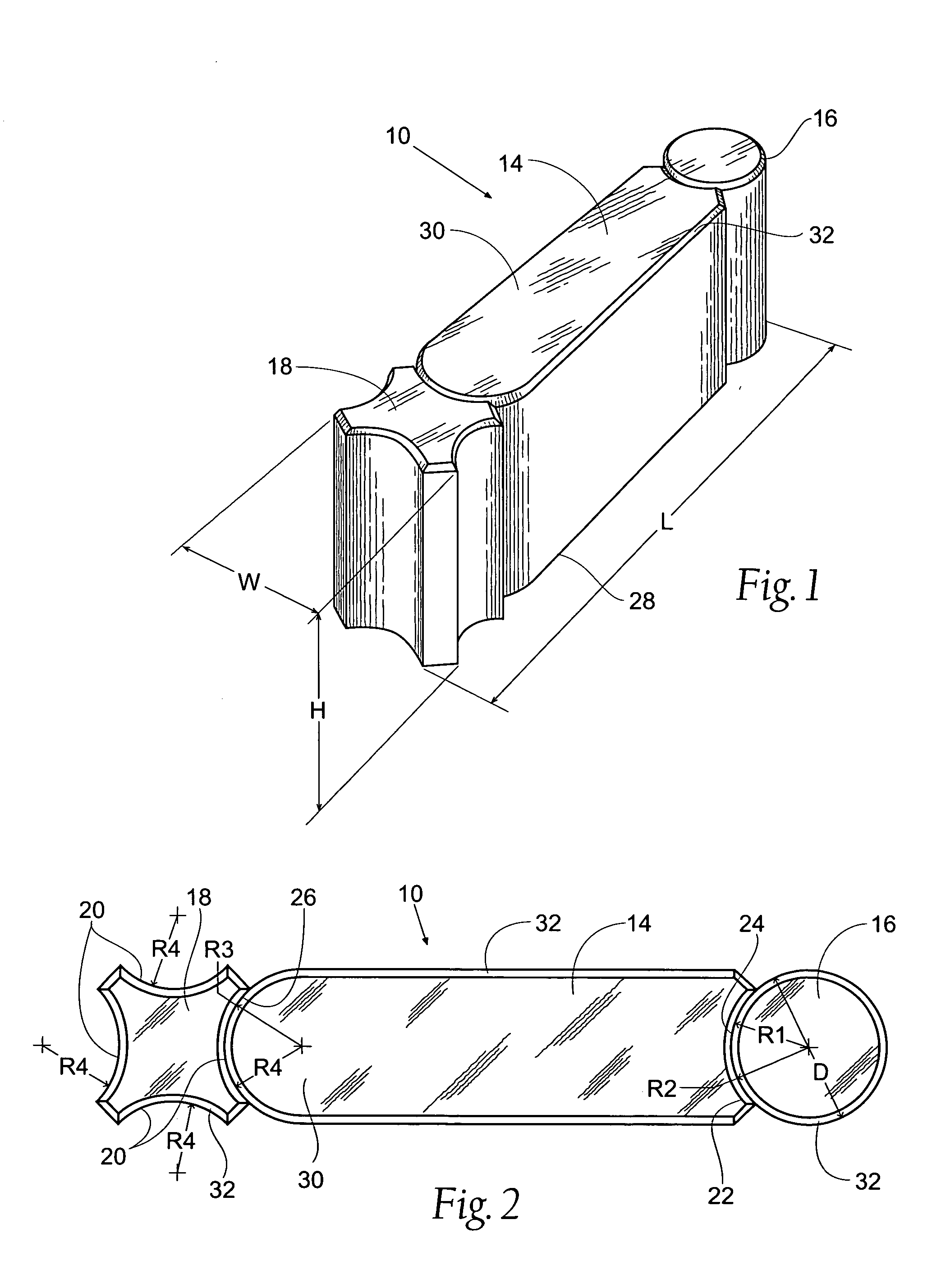
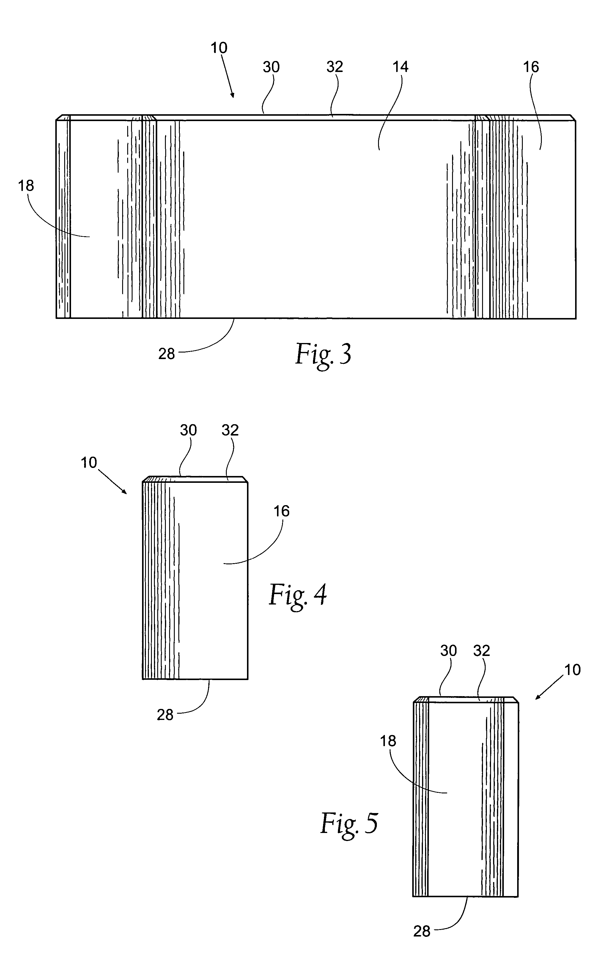
A decorative modular masonry unit includes a central web, a cylindrical end portion, and a second end portion providing a plurality of concave or recessed grooves. The cylindrical end portion of one modular masonry unit articulates with a recessed groove of a like-shaped unit to form a modular structure. A series of units may be assembled into patterns of varying size and configuration.

Description

RELATED APPLICATIONS [0001] This application claims the benefit of provisional U.S. Application Ser. No. 60 / 500,616, filed Sep. 5, 2003, and entitled “Decorative Modular Masonry Block.”FIELD OF THE INVENTION [0002] The invention relates generally to masonry blocks. In particular, the invention relates to modular masonry units for forming raised garden and flowerbeds. BACKGROUND OF THE INVENTION [0003] Masonry blocks for forming raised garden and flowerbeds are well known. The blocks delineate the garden from surrounding landscape and serve to retain soil and vegetation in a specified area. It is desirable such garden beds are aesthetically appealing and that such blocks can be readily articulated in aesthetic patterns of various sizes and configurations. It is also desirable that the configuration or arrangement of such units can be easily changed. Conventional units typically permit articulation between adjacent units within a limited range of angles. Therefore, there are a limited...

Claims


Application Information

Patent Timeline
Patent Type & Authority Applications(United States)
IPC IPC(8): A01G9/28B44C5/00E04B2/02E04C1/39
CPCA01G1/08B44C5/00E04F2201/09E04C1/395E04F2201/0594E04B2002/0263A01G9/28
Inventor WHITSON, ROBERT L.
Owner BEND INDS
Learn More