Spread spectrum clock generator

Inactive Publication Date: 2005-03-10
SAMSUNG ELECTRONICS CO LTD
View PDF15 Cites 14 Cited by
  • Summary
  • Abstract
  • Description
  • Claims
  • Application Information

AI Technical Summary

Benefits of technology

will become more readily apparent from the detailed descript

Problems solved by technology

System clocks such as this can be a source of unwanted electromagnetic interference (EMI).
EMI can cause problems in electronic circuits, as it interferes with signal transmission.
PLLs vary the voltage to a voltage controlled oscillator (VCO), causing varying delays in the clock.
This approach may be somewhat limited, as it only allows for two fixed frequencies to be used, and does not allow programmable control.
However, these loads cannot be changed linearly to adjust the clock frequency as needed.

Method used


Image

  • Spread spectrum clock generator
  • Spread spectrum clock generator
  • Spread spectrum clock generator

Examples


Embodiment Construction

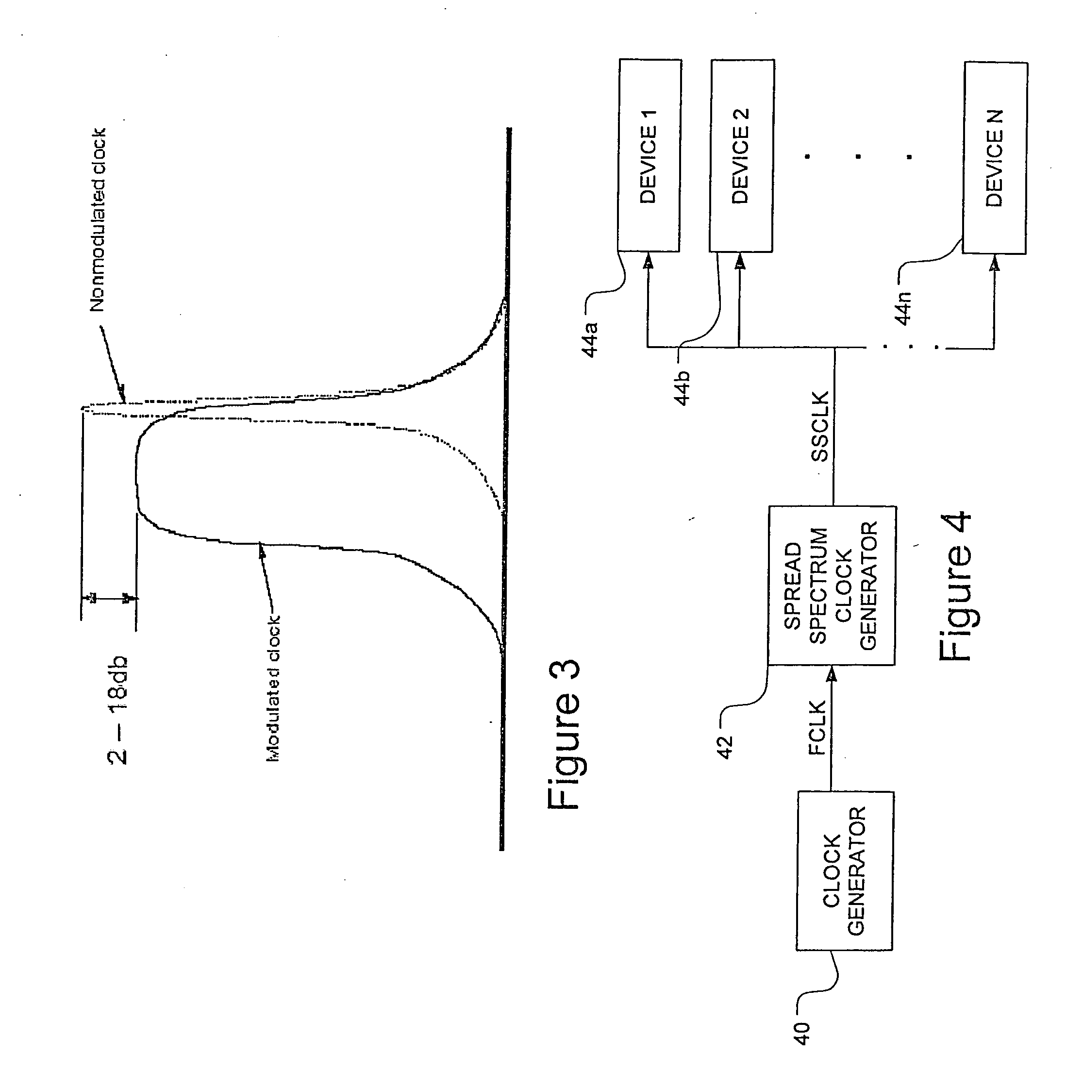
FIG. 3 shows the basis of the problem with nonmodulated clock signals. The energy spike from a nonmodulator clock may have an amplitude of two to eighteen dB beyond that of a modulated, or spread spectrum, clock signal. This difference causes a much higher level of EMI that can have negative effects on electronic components and systems such as memory systems. Examples discussed herein may rely upon memory system components and methods, but are merely intended as examples, and it must be understood that application of embodiments of the invention are not limited to memory systems.

An example of such a system is shown in FIG. 4. A clock generator 40 generates a fixed frequency clock, FCLK, that is used by the spread spectrum clock generator (SSCG) 42. SSCG 42 produces a spread spectrum clock and is in turn used by electronic devices 44a through 44n. In a memory system, the devices 44a-44n may be memory banks or memory module or memory device or registers used to store data.

Alternati...


PUM


Abstract

A spread spectrum clock generator includes a non-volatile memory to store control codes corresponding to a predetermined delay. A delay circuit receives a control code having a predetermined number of bits that determine a delay to apply to a fixed clock signal a period of time. The delay mitigates the electromagnetic interference caused by a periodic clock signal.

Description

This application claims priority from Korean patent application number 2003-62863 filed Sep. 8, 2003 that we incorporate herein by reference. BACKGROUND OF THE INVENTION 1. Field of the Invention The present invention relates to a spread spectrum clock generator and a method of generating a spread spectrum clock. 2. Description of the Related Art A clock generator, such as 10 in FIG. 1, generally comprises a clock source 100 and a phase-locked loop (PLL) 102. This generator 10 generates a system clock usually having square waves and a 50% duty cycle. The system clock is then used in many different types of systems, such as a memory system including a memory module 14 and a memory controller 12. System clocks such as this can be a source of unwanted electromagnetic interference (EMI). EMI can cause problems in electronic circuits, as it interferes with signal transmission. As technology improves, circuits can operate faster, requiring faster clocks that in turn generate more EM...

Claims


Application Information

Patent Timeline
IPC IPC(8): G06F1/08H03K5/1252H03K5/00H03K5/13H03K5/156H04B1/69H04B15/02
CPCG06F1/08H03K5/156H03K5/133H04B15/02H04B2215/067H03K2005/00071H03K5/1252
Inventor KIM, KYU-HYOUNCHUNG, HOE-JU
Owner SAMSUNG ELECTRONICS CO LTD
Why Eureka
Try Eureka