Pulp pump

a centrifugal pump and pulp technology, applied in the direction of positive displacement liquid engine, piston pump, liquid fuel engine, etc., can solve the problems of deteriorating the capacity affecting the efficiency of the pulp pump, and causing problems such as pulp pump becoming relatively complicated and expensiv

Inactive Publication Date: 2005-03-10
VALMET TECH INC
View PDF10 Cites 10 Cited by
  • Summary
  • Abstract
  • Description
  • Claims
  • Application Information

AI Technical Summary

Problems solved by technology

Gas following along with the pulp creates problems during pumping of pulp by centrifugal pumps.
The gas in the pulp forms bubbles, which are accumulated in front of the impeller and thereby deteriorate the capacity of the pump.
In cases where a separate vacuum pump is used, the pulp pump becomes relatively complicated and expensive, because the system comprises more components compared to a pulp pump, where the vacuum impeller is mounted on the shaft of the pulp pump.
This requires more or less extreme designs, with the concurrent risk of faulty functioning.
The maintenance will also thus be more complicated and expensive.

Method used


Image

  • Pulp pump
  • Pulp pump

Examples


Embodiment Construction

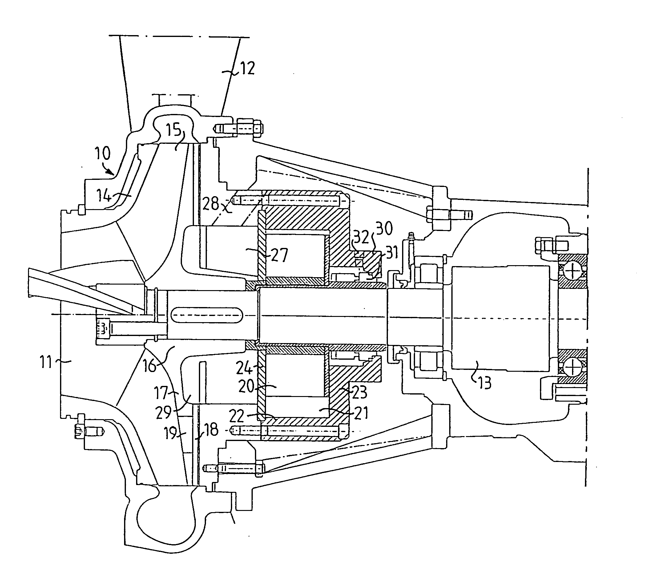
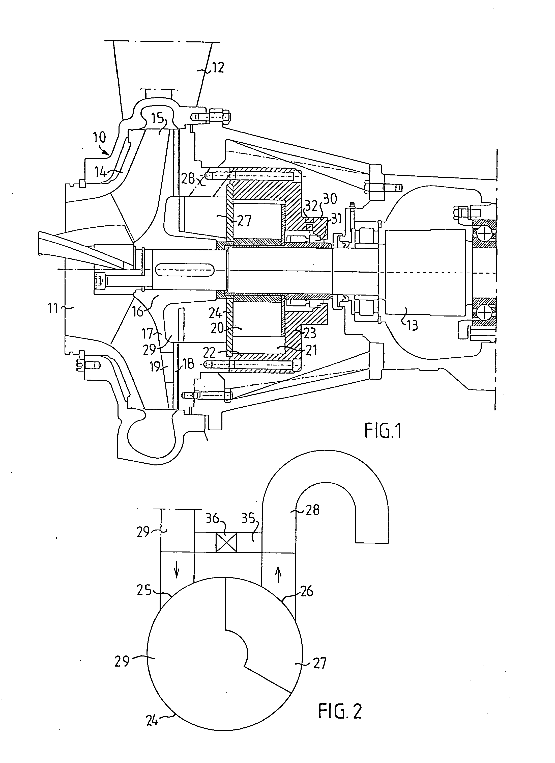
[0012] The centrifugal pump shown in FIG. 1 comprises a pump housing 10 with an inlet 11 and an outlet 12 for the pulp suspension. Such pumps are used at relatively high pulp concentration, for example from about 6% to 18%. On a rotary shaft 13 in the pump housing 10 an impeller 14 is mounted, the pump blades 15 of which extend from a hub 16 outward along a wheel disk 17. On the rear side of the wheel disk 17 back blades 18 are located. The wheel disk 17 is further formed with openings 19 for the discharge of gas collected in front of the impeller.

[0013] Behind the impeller 14 a vacuum impeller with vacuum impeller blades 20 is located, which impeller is surrounded by a vacuum pump housing 21. This vacuum pump housing 21 comprises an outer cylindrical wall 22, a rear wall 23 and a front wall 24. The cylindrical wall 22 is eccentric in relation to the vacuum impeller blades 20, so that a liquid ring pump is formed. In the front wall 24 a suction port 25 for gas and an exhaust port 2...


PUM

PropertyMeasurementUnit
vacuumaaaaaaaaaa
concentrationaaaaaaaaaa
distanceaaaaaaaaaa

Abstract

Centrifugal pumps for pumping a pulp suspension and conducting gas away from the pulp suspension are disclosed including a pump housing having an inlet and an outlet, a rotary shaft, an impeller mounted on the rotary shaft within the pump housing, the impeller including a hub and pump blades extending outwardly from the hub, a wheel disk adjacent to the impeller so that the pump blades extend outwardly along the wheel disk, a vacuum impeller within the pump housing behind the wheel disk and including a vacuum pump housing, vacuum impeller blades, a seal for sealing the vacuum pump housing to the rotary shaft, the vacuum pump housing including a suction port for drawing gas into the vacuum pump housing and an exhaust port for expelling gas therefrom.

Description

FIELD OF THE INVENTION [0001] The present invention relates to a centrifugal pump for pulp suspensions of lignocellulosic material. More particularly, the present invention relates to a pump where gas, such as air, can be separated from the pulp in the pump. [0002] Gas following along with the pulp creates problems during pumping of pulp by centrifugal pumps. The gas in the pulp forms bubbles, which are accumulated in front of the impeller and thereby deteriorate the capacity of the pump. This problem can be overcome by evacuating the gas from the space in front of the impeller, for example by means of vacuum pumps such as the liquid-ring pump type. Such a pump can be a separate vacuum pump, the suction pipe of which is connected to the sealing space of the pulp pump, or it can be formed with a separate vacuum impeller in the form of a liquid-ring impeller, which is mounted on the shaft of the pulp pump, so that for both impellers a common operation is obtained. [0003] In cases wher...

Claims


Application Information

Patent Timeline
Patent Type & Authority Applications(United States)
IPC IPC(8): D21D5/26F04D9/04F04D29/12
CPCD21D5/26F04D29/128F04D9/041
Inventor DANIELSSON, PETERALGERS, BENGTBANIAMERI, AMIR
Owner VALMET TECH INC
Why Eureka
Try Eureka