Roof flashing assembly

a technology for roofs and assemblies, applied in the direction of roof coverings, snow traps, building components, etc., can solve the problems of roof leakage, costly repairs for building owners and roofers, and eventually leakage into the structur

Inactive Publication Date: 2005-03-17
THALER KEN
View PDF7 Cites 88 Cited by
  • Summary
  • Abstract
  • Description
  • Claims
  • Application Information

AI Technical Summary

Benefits of technology

[0015] In a further additional feature, the outer flange portion has at least one resilient ring seal member downwardly depending from its lower surface. The at least one ring seal member has a generally triangular profile when viewed in cross-section. Additionally, the at least one ring seal member tapers downwardly from the lower surface of the outer flange portion to terminate at a free edge. The free edge of the at least one ring seal member is urged to bear against the roof surface in frictional sealing engagement therewith when the roof flashing assembly is o...

Problems solved by technology

Roof leaks result in costly repairs for building owners and roofers.
In northern climates condensation and leaks at roof protrusions caused by roof flashing products are the most common reason for roofing failure.
It is believed that condensation problems alone are responsible for as much as 80 percent of all roof leaks.
The ice thus formed melts during the spring and eventually leaks into the structure.
Despite the availability of insulated roof flashings, many installers elect, because of cost, to use non-insulated flashings.
However, even when insulation is used, it has been found that condensation problems tend to persist to an unacceptable degree.
Although there often is vapor barrier, insulation material and flashing to protect ...

Method used


Image

  • Roof flashing assembly
  • Roof flashing assembly
  • Roof flashing assembly

Examples


Embodiment Construction

[0030] The description, which follows, and the embodiments described therein, are provided by way of illustration of an example, or examples of particular embodiments of principles and aspects of the present invention. These examples are provided for the purposes of explanation, and not of limitation, of those principles and of the invention. In the description that follows, like parts are marked throughout the specification and the drawings with the same respective reference numerals.

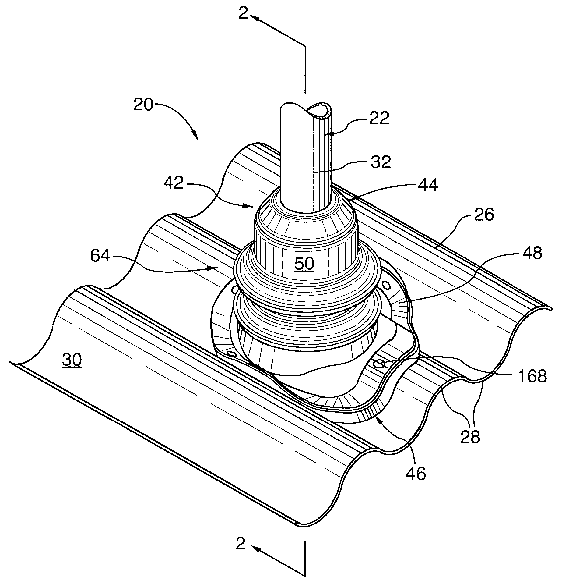
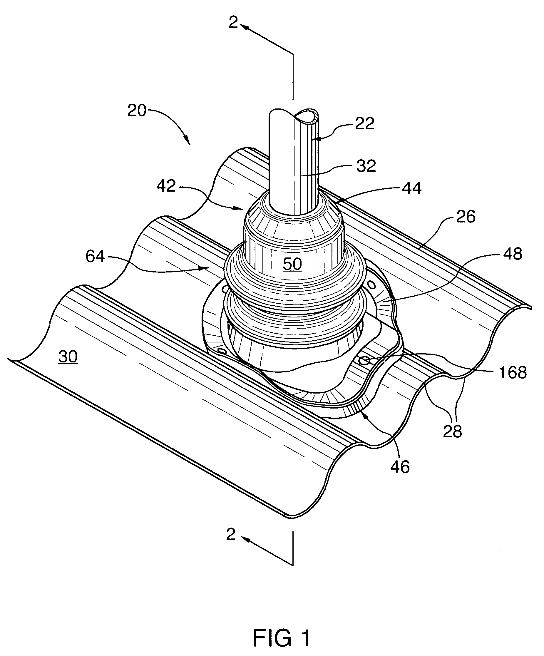
[0031] Referring to FIGS. 1 and 2, a roof flashing assembly is generally designated with reference numeral 20. During installation, the roof flashing assembly 20 is operatively mounted in surrounding relation with an elongate projection 22 and securely anchored to a sloped roof surface 26 of a building or structure (not shown) to prevent moisture from penetrating below the level of the sloped roof surface 26 and from ultimately seeping into the building.

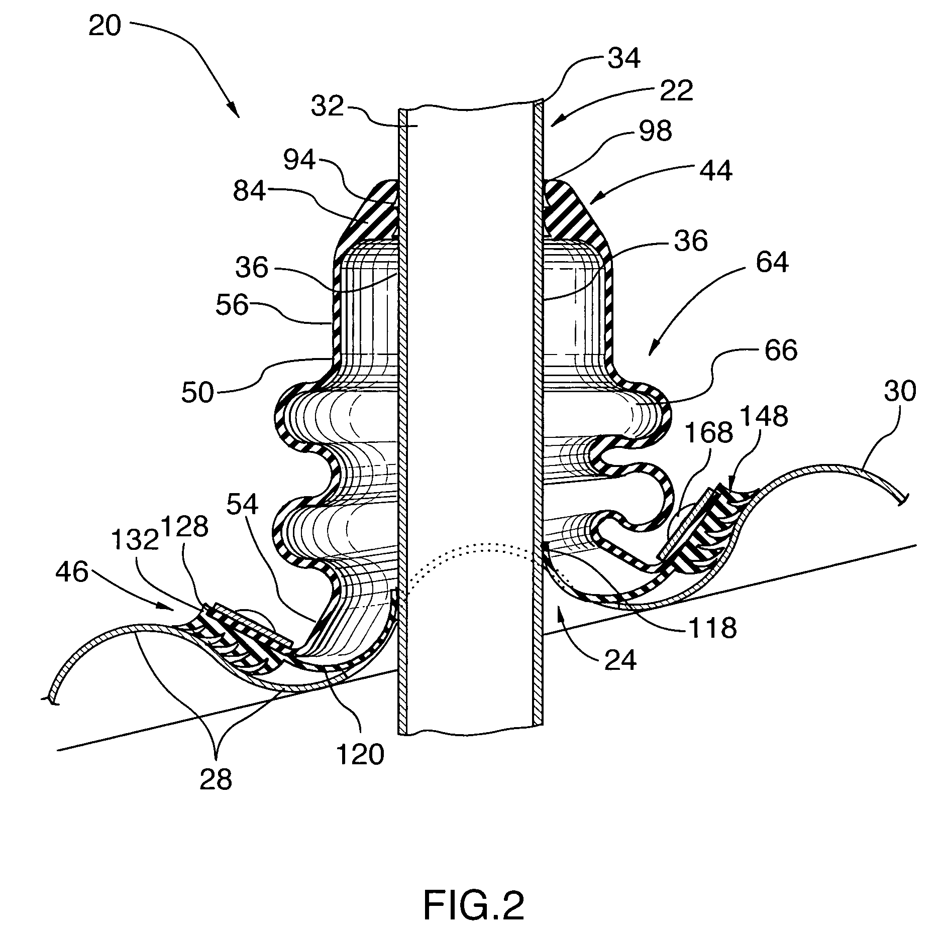
[0032] As best seen in FIG. 2, the projection 2...


PUM


Abstract

The present invention relates to a roof flashing assembly for use on a sloped roof surface having an elongate projection extending substantially upwardly therefrom in skewed relation thereto. The roof flashing assembly has a resilient, flexible, sleeve sized to fit over, and surround, the projection. The sleeve has a base portion, a neck portion and a passageway defined therebetween for receiving the projection therethrough. A bellows tube is formed on the neck portion to permit the sleeve to flex adaptively to accommodate for the skewed orientation of the projection relative to the sloped roof surface. The roof flashing assembly also includes a grommet which is positionable in surrounding relation with the projection. The grommet has three beveled lip members, which frictionally sealingly engage the exterior surface of the projection when urged in abutting relation therewith. An annular gasket positionable below the base portion of the sleeve, is also provided. The gasket frictionally sealingly engages the external surface of the projection. When urged in abutting relation with the sloped roof surface, flexible ring seal members formed on the underside of the gasket create a watertight seal with the roof surface. During installation, anchoring means are used to secure the sleeve and the gasket to the sloped roof surface.

Description

FIELD OF THE INVENTION [0001] The present invention relates to a roof flashing assembly used to provide watertight and weather resistant seals between a sloped roof surface and an upwardly projecting member such as a pipe or vent stack. BACKGROUND OF THE INVENTION [0002] Roof flashing is conventionally used to provide a waterproof and weather resistant seal around pipes, vent stacks and other elongate members projecting through roofs. Roof flashing is generally constructed from sheet metal, flexible moulded rubber or other synthetic material formed in an appropriate shape to surround such projecting members, and is normally made to extend slightly above the level of the roof, to limit the penetration of precipitation therebelow. [0003] Roof leaks result in costly repairs for building owners and roofers. In northern climates condensation and leaks at roof protrusions caused by roof flashing products are the most common reason for roofing failure. It is believed that condensation prob...

Claims


Application Information

Patent Timeline
IPC IPC(8): E04D13/147
CPCE04D13/1476
Inventor THALER, KEN
Owner THALER KEN
Why Eureka
Try Eureka