
Tool holding and displaying device

a technology for displaying devices and tools, which is applied in the direction of transportation and packaging, tray containers, rigid containers, etc., can solve the problems of no longer being held or supported by tools, the hook may be easily disengaged from the supporting bracket, and the support bracket may no longer be attached or supported

Inactive Publication Date: 2005-03-24
CHIANG KUO CHUAN
View PDF9 Cites 18 Cited by
  • Summary
  • Abstract
  • Description
  • Claims
  • Application Information

AI Technical Summary

Benefits of technology

[0014] The primary objective of the present invention is to provide a tool holding and displaying device for locking tools with an anti-theft locking device, and for allowing the tools to be removed from the displaying device when required.

Problems solved by technology

The supporting bracket may no longer be attached to or supported by the suspension plates, and the tools may no longer be held or supported or displayed with the suspension plates after the stubs have been cut from the supporting bracket.
However, the hooks may be easily disengaged from the supporting bracket, and may not be provided for anti-theft purposes, such that additional anti-theft devices are required to be attached to the suspension plates and the supporting bracket, in order to secure the suspension plates and the supporting bracket together.
The hooks may be provided to support the tools to the suspension plates, but may not be easily engaged into the suspension plates.
However, the hooks or catches may not be easily disengaged from the supporting bracket when required, and the tools also may not be easily disengaged or removed from the suspension plates in order to obtain the tools from the suspension plates.

Method used


Image

  • Tool holding and displaying device
  • Tool holding and displaying device
  • Tool holding and displaying device

Examples


Embodiment Construction

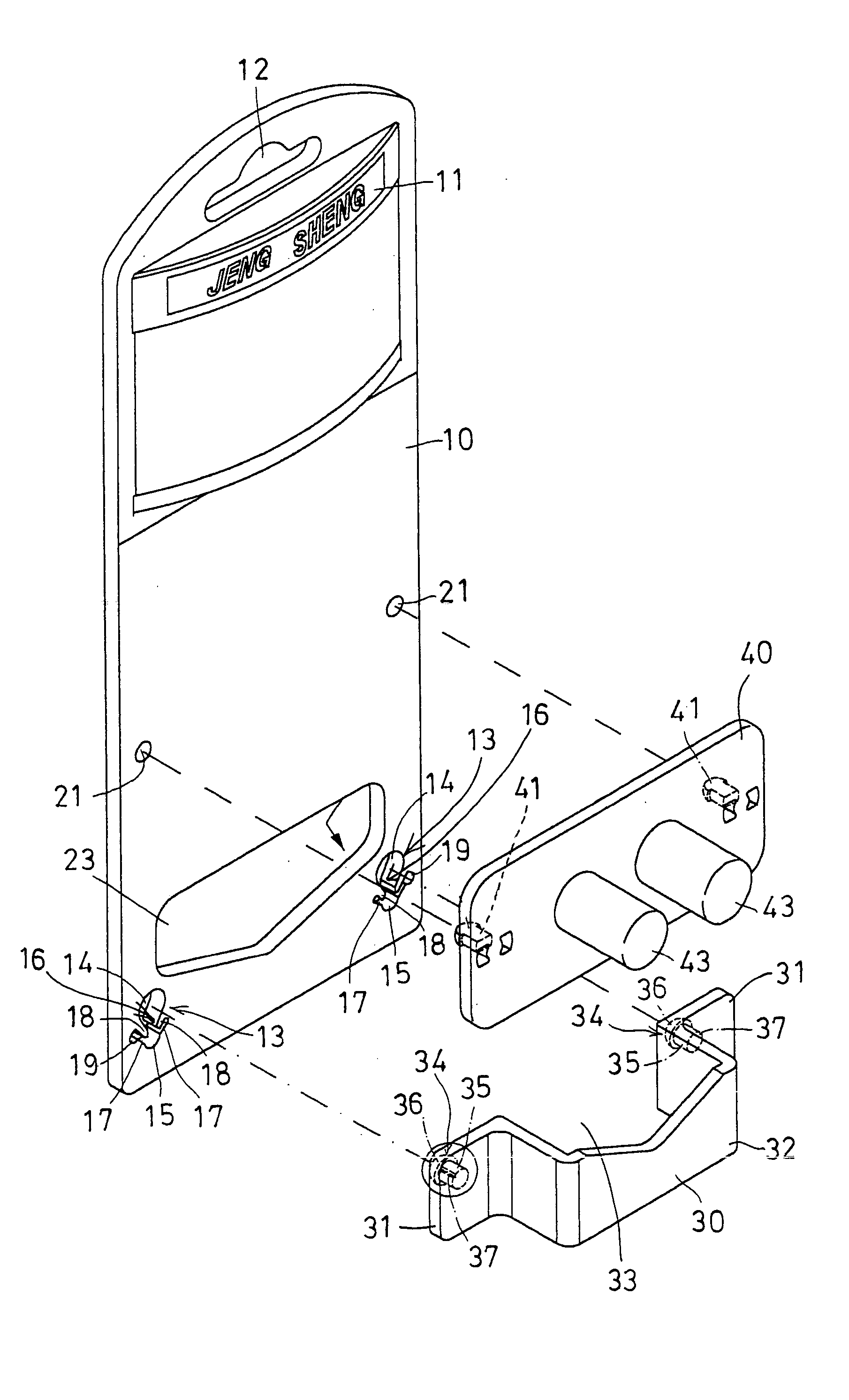
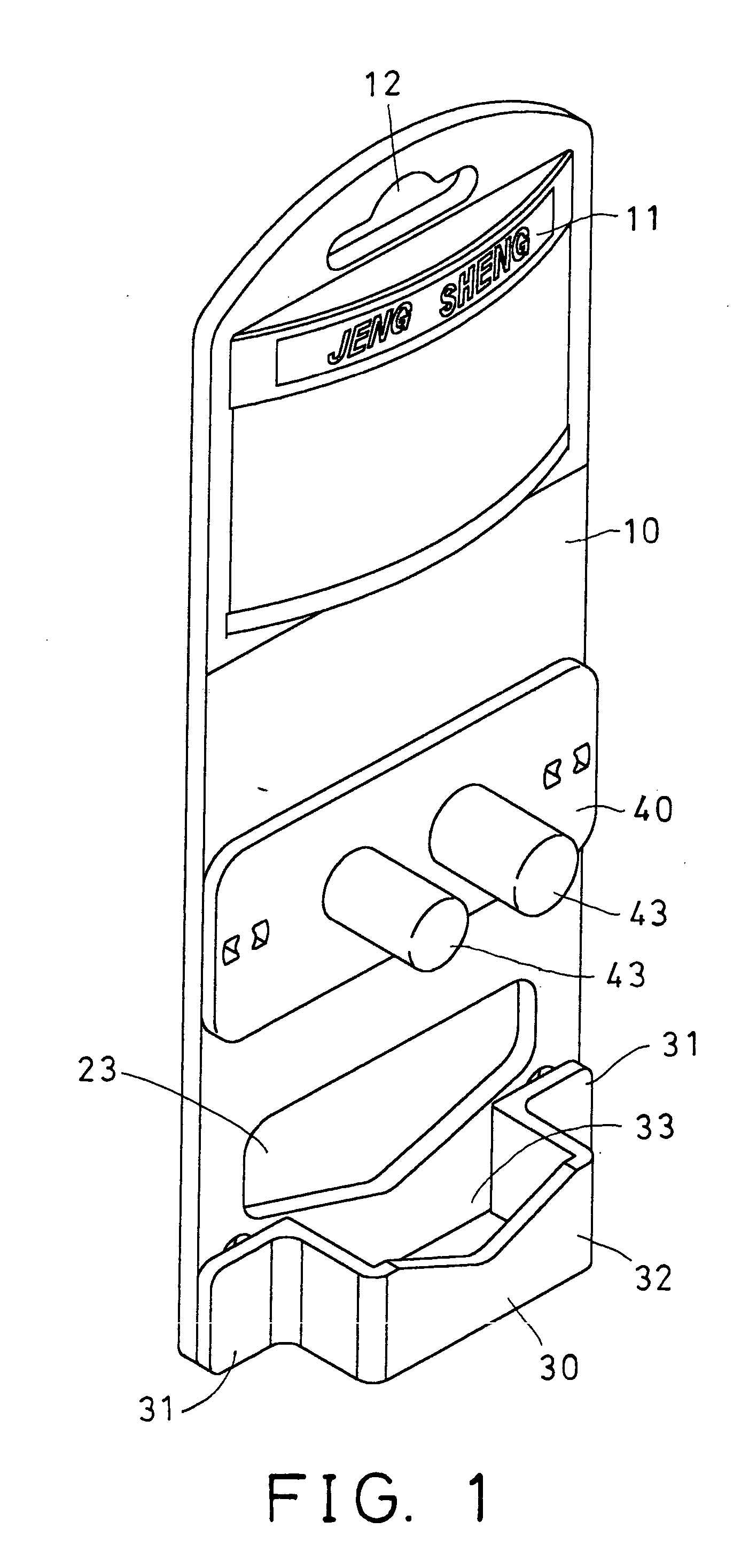
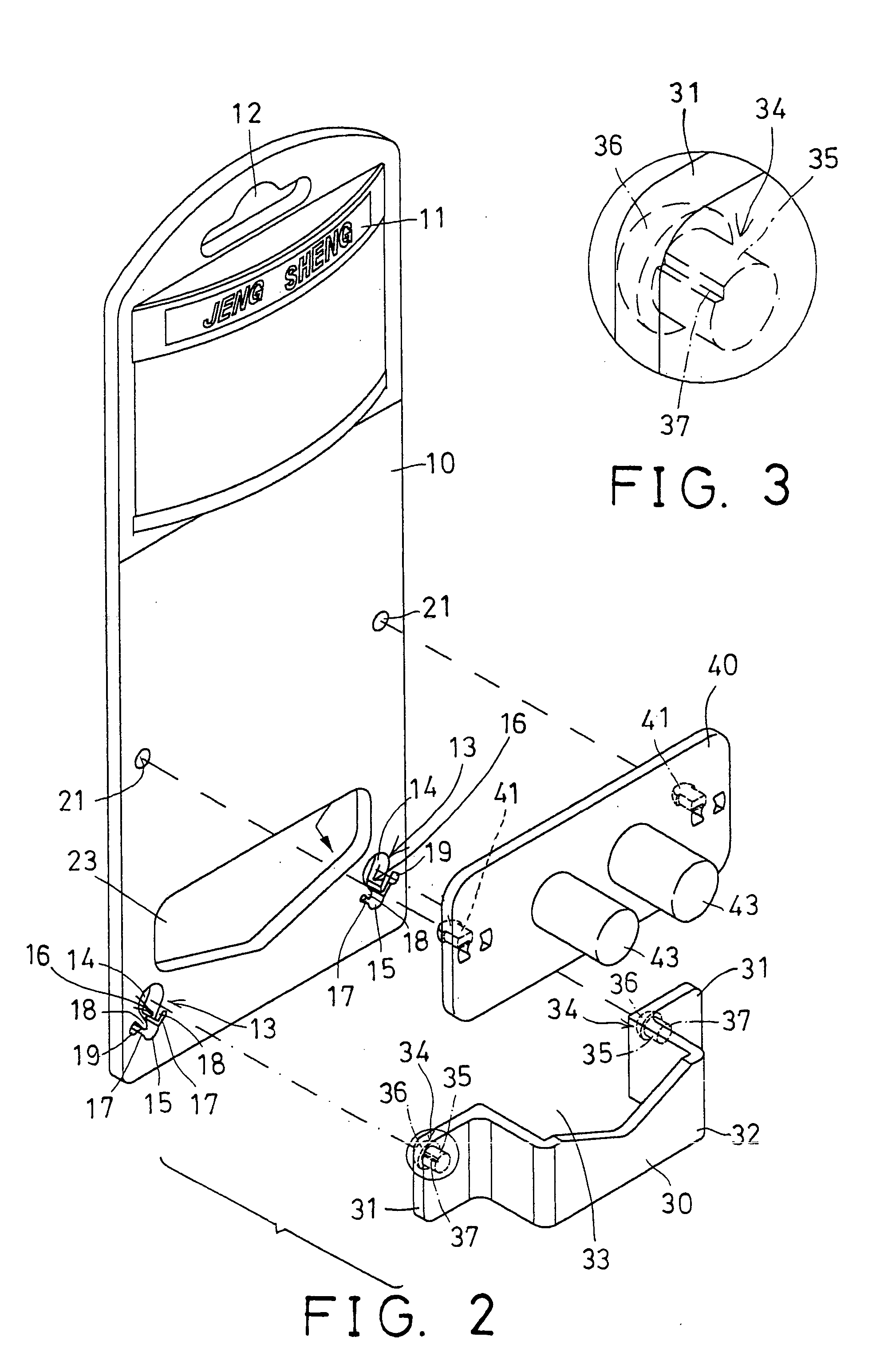
[0028] Referring to the drawings, and initially to FIGS. 1-6, a tool holding and displaying device in accordance with the present invention comprises a suspension plate 10 including an area 11 for applying with different patterns, colors, or the like, or for attaching marks thereon, and including a suspension slot 12 formed therein for hanging or suspension purposes.

[0029] The plate 10 further includes one or more, such as two locking grooves 13 formed therein, and each having an upper orifice 14 and a lower aperture 15 formed therein and communicating with each other, to form a narrower neck portion 16 therebetween. The upper orifice 14 of the plate 10 includes an inner diameter greater than that of the lower aperture 15 of the plate 10.

[0030] The plate 10 further includes two slots 17 formed on both sides of each of the locking grooves 13 thereof, in order to form or define two spring arms 18 which may also be used to form or define the narrower neck portion 16 of the locking gr...


PUM


Abstract

A tool holding and displaying device includes a plate having a narrower neck portion formed between an upper orifice and a lower aperture. The upper orifice of the plate includes an inner diameter greater than that of the lower aperture of the plate, and a bracket includes a latch having an enlarged head formed on a pin for engaging into the upper orifice of the plate. The enlarged head of the latch is greater than the lower apertures of the plate, to engage with the plate, and to anchor the bracket to the plate. The plate includes one or more spring arms to engage with the pin of the latch of the bracket, to lock the latch of the bracket to the plate.

Description

BACKGROUND OF THE INVENTION [0001] 1. Field of the Invention [0002] The present invention relates to a tool holding and displaying device, and more particularly to a tool holding and displaying device for locking tools, and for allowing the tools to be removed from the displaying device when required. [0003] 2. Description of the Prior Art [0004] Various kinds of typical tool holding and displaying devices have been developed for locking tools with an anti-theft locking device, and for allowing the tools to be removed from the displaying device when required. [0005] For example, U.S. Pat. No. 5,996,817 to Kao discloses one of the typical tool holding and displaying devices comprising a supporting bracket having two stubs for engaging through holes of suspension plates, and for attaching or supporting tools to the suspension plates. [0006] However, the stubs should be cut from the supporting bracket before the tools may be disengaged from the supporting bracket. The supporting bracke...

Claims


Application Information

Patent Timeline
Patent Type & Authority Applications(United States)
IPC IPC(8): B65D73/00
CPCB65D2211/00B65D73/0064
Inventor CHIANG, KUO CHUAN
Owner CHIANG KUO CHUAN
Learn More