

Session control system, communication terminal and servers
- Summary
- Abstract
- Description
- Claims
- Application Information
AI Technical Summary
Benefits of technology
Problems solved by technology
Method used
Image

Examples
embodiment 1
[0044]FIGS. 21A-21B show packet formats of a SIP packet used for communication according to the present invention. The SIP packet is composed of a SIP payload portion 503, a SIP header portion 502, a layer 4 header (an UDP header 501 or a TCP header 504) and an IP header (an IPv4 header 500 or an IPv6 header 505).
[0045]FIG. 22 shows an example of the SIP header portion 502 of the SIP packet used in the present invention.
[0046]FIG. 23 shows an example of the payload portion 503 of the SIP packet used in the present invention. A negotiation on communication abilities such as a support service and a support protocol between two terminals is performed by using the payload portion. In the present payload, the IPv4 is designated by a “c” header as a communication protocol. If the communication abilities of the two terminals are different, e.g., whether or not another procedure should be selected is judged from this field.
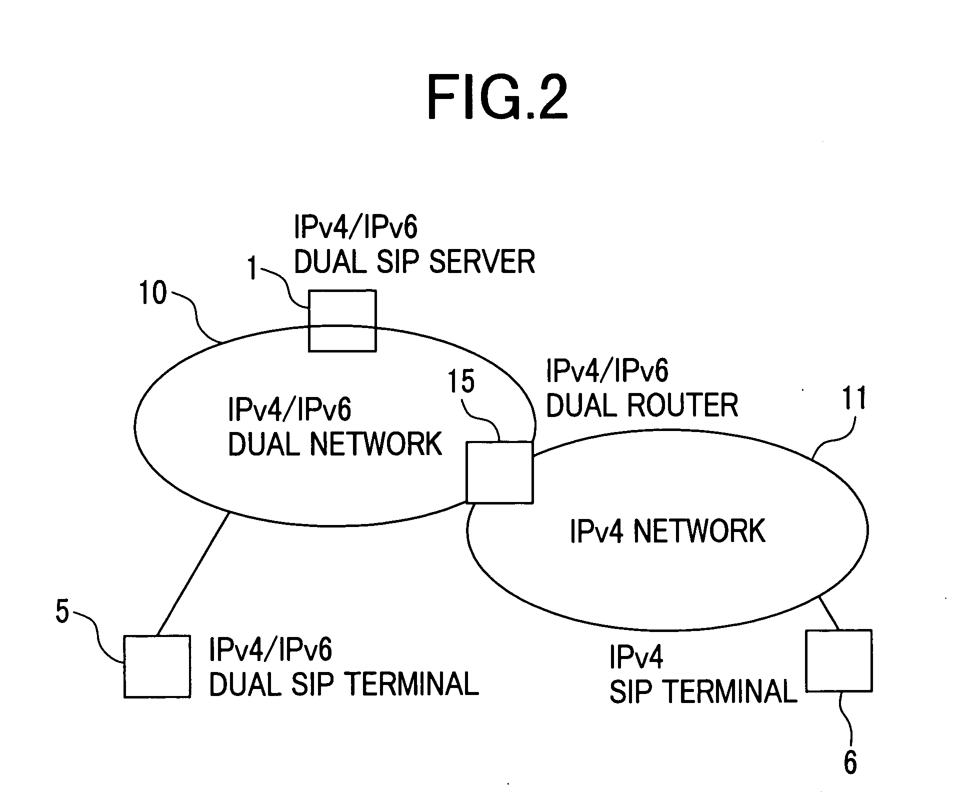
[0047]FIG. 24 is a structural view of an IPv4 / IPv6 dual SIP serve...
embodiment 1-1
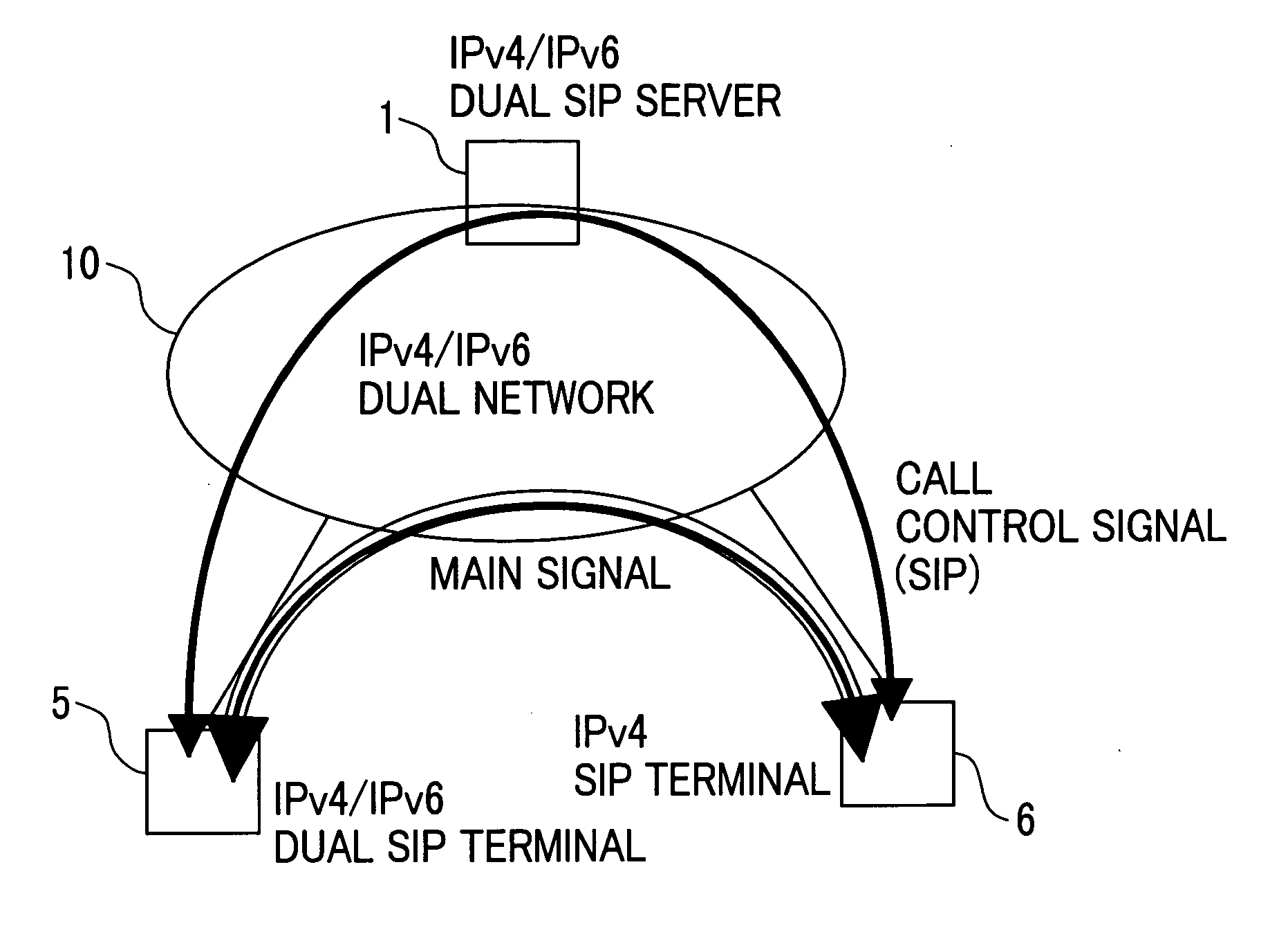
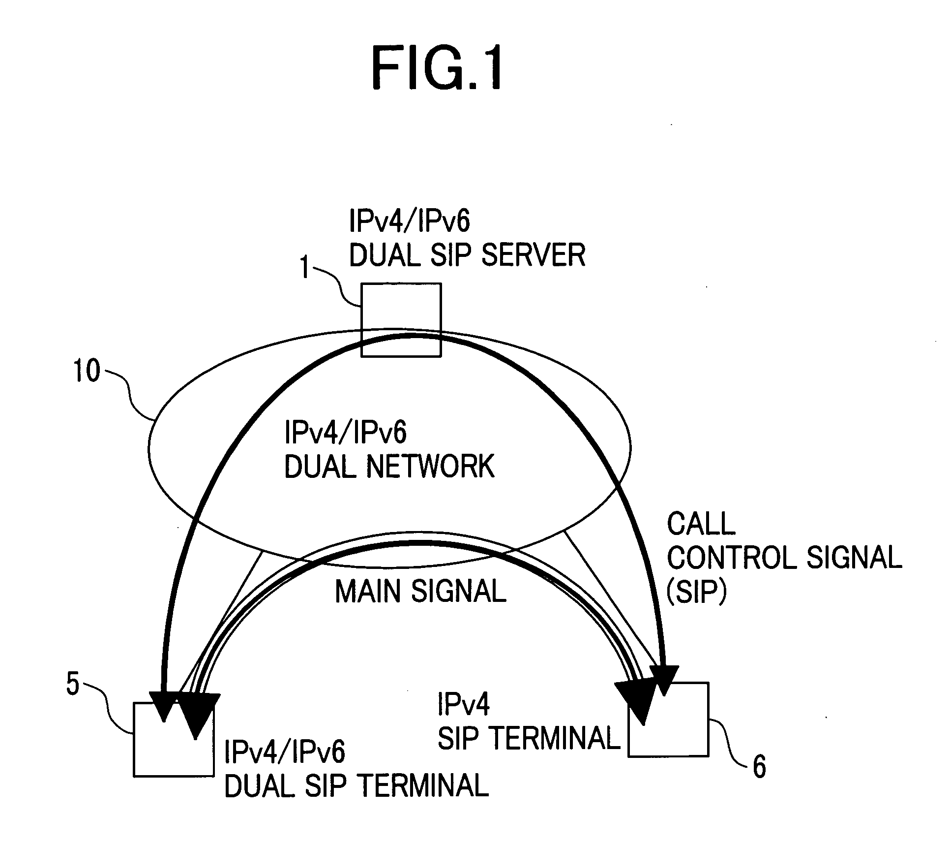
[0070]FIGS. 3 and 4 show an embodiment of a communication procedure in the case where the IPv4 / IPv6 dual SIP terminal 5 according to the present invention and the IPv4 SIP terminal 6 perform communication therebetween. FIG. 3 shows the sequence of a call from the IPv4 / IPv6 dual SIP terminal 5 and FIG. 4 shows the sequence of a call from the IPv4 terminal. In the drawings, the sequence indicated by the solid lines shows a communication procedure using IPv6 packets and the sequence indicated by the broken lines shows a communication procedure using IPv4 packets.
[0071] In the present embodiment, each of the IPv4 / IPv6 dual SIP terminal 5 and the IPv4 SIP terminal 6 performs a registration to the same IPv4 / IPv6 dual SIP server 1.
[0072] The IPv4 / IPv6 dual SIP terminal 5 performs a registration to the IPv4 / IPv6 dual SIP server 1 in accordance with an IPv6 register procedure (REGISTER) (41) and an IPv4 register procedure (43) based on each of the IPV4 and IPV6 protocols. This allows the I...
embodiment 1-2
[0077]FIGS. 5 and 6 show an embodiment of a communication procedure in the case where the IPv4 / IPv6 dual SIP terminal 5 according to the present invention and the IPv4 SIP terminal 6 perform communication therebetween. FIG. 5 shows the sequence of a call from the IPv4 / IPv6 dual SIP terminal 5 and FIG. 6 shows the sequence of a call from the IPv4 terminal. In the drawings, the sequence indicated by the solid lines shows a communication procedure using IPv6 packets and the sequence indicated by the broken lines shows a communication procedure using IPv4 packets.
[0078] The present embodiment shows the case where each of the IPv4 / IPv6 dual SIP terminal 5 and the IPv4 SIP terminal 6 performs a registration (81,82) to the same IPv4 / IPv6 dual SIP server 1. According to the present embodiment, as shown in FIG. 5, the IPv4 / IPv6 dual SIP terminal 5 registers an IPv4 address and an IPv6 address simultaneously in accordance with an IPv4 / IPv6 dual register procedure (81). Consequently, a packet...
PUM
 Abstract
Description
Claims
Application Information