Temporary shelter

a temporary shelter and shelter technology, applied in the field of temporary shelters, can solve the problems of homeless persons still facing a problem of wher

Inactive Publication Date: 2005-03-31
LAMBERT GEOFFREY
View PDF8 Cites 63 Cited by
  • Summary
  • Abstract
  • Description
  • Claims
  • Application Information

AI Technical Summary

Problems solved by technology

The homeless persons are still faced with

Method used


Image

  • Temporary shelter
  • Temporary shelter
  • Temporary shelter

Examples


Embodiment Construction

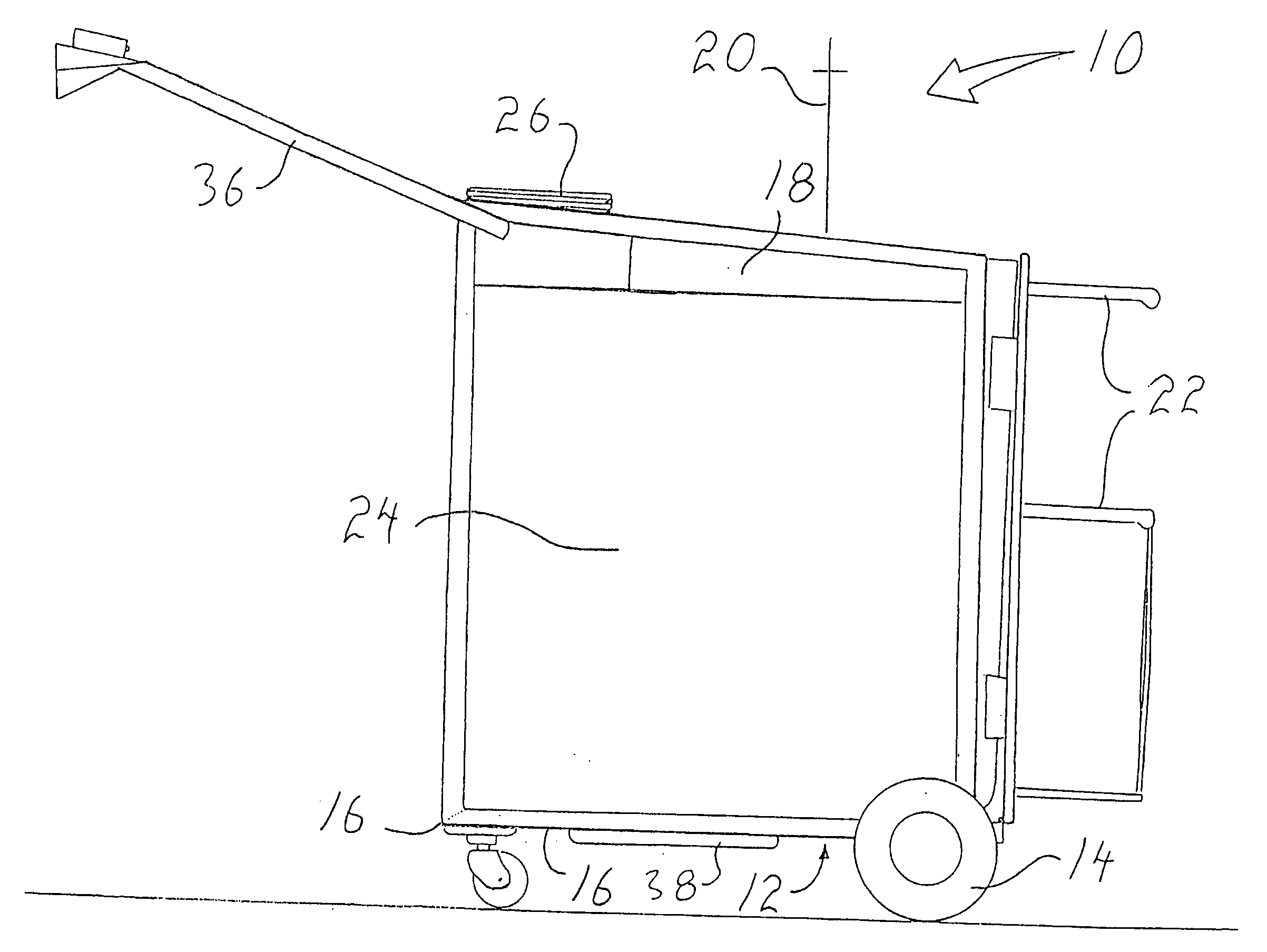
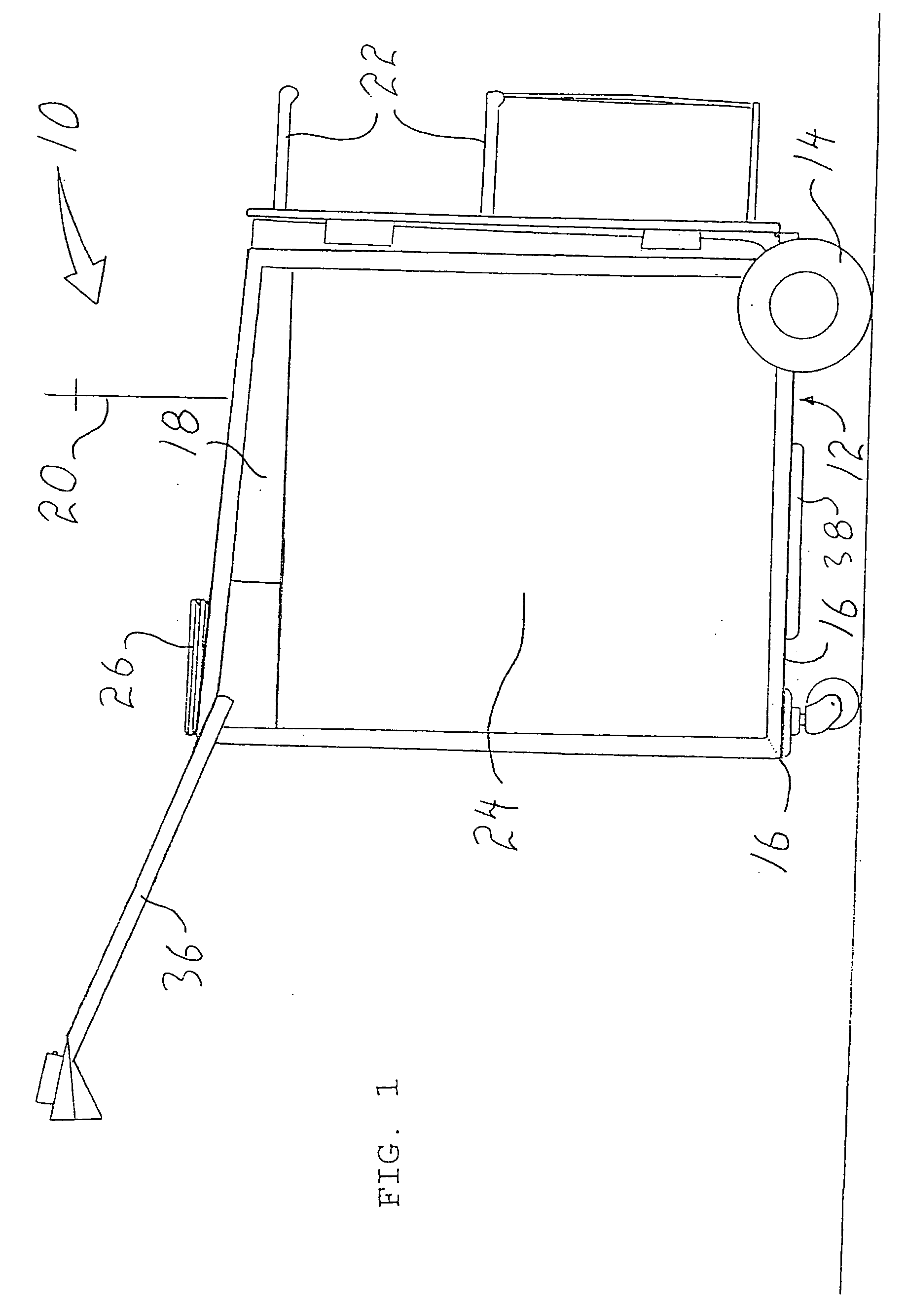
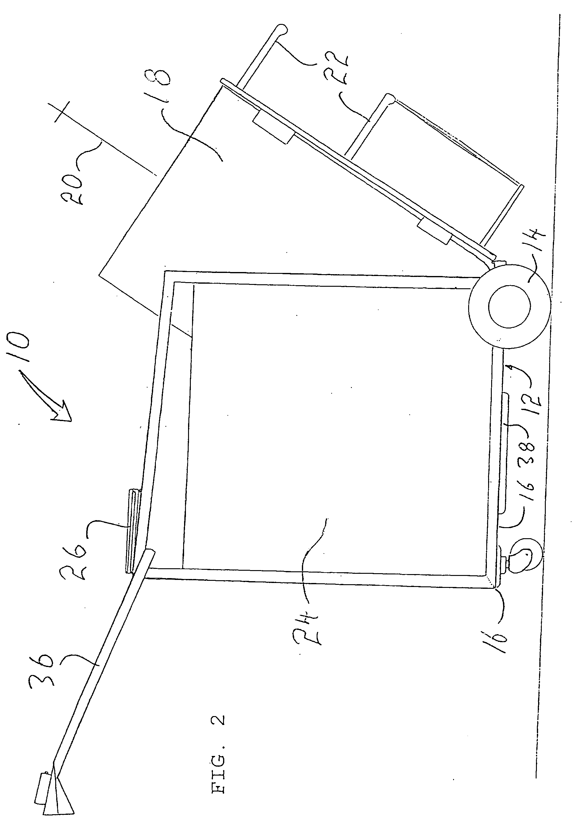
[0011] The preferred embodiment, a temporary shelter generally identified by reference numeral 10, will now be described with reference to FIGS. 1 through 4.

[0012] Structure and Relationship of Parts:

[0013] Referring to FIG. 1, shelter 10 has a rectangular base 12 with underlying wheels 14 and four peripheral edges 16. A tubular enclosure 18 with a longitudinal axis 20 and radial support legs 22 is pivotally mounted to one of edges 16 of base 12. Pivotal movement occurs between a first position (illustrated in FIG. 1) in which longitudinal axis 20 is in a substantially vertical collection orientation with tubular enclosure 18 resting upon base 12 and a second position (illustrated in FIG. 3) in which longitudinal axis 20 is in a substantially horizontal sleeping orientation with tubular enclosure 18 resting upon support legs 22 adjacent to base 12. Referring to FIG. 1, base 12 is further adapted with a peripheral wall 24 which extends upwardly from three of edges 16 enclosing all ...


PUM


Abstract

A temporary shelter includes a rectangular base with underlying wheels and four peripheral edges. A tubular enclosure with a longitudinal axis and radial support legs. The tubular enclosure is pivotally mounted to one of the edges of the base for pivotal movement between a first position and a second position. In the first position, the longitudinal axis is in a substantially vertical collection orientation with the tubular enclosure resting upon the base. In the second position, the longitudinal axis is in a substantially horizontal sleeping orientation with the tubular enclosure resting upon the support legs adjacent to the base. A peripheral wall extends upwardly from three of the edges enclosing all but the one edge of the base where the tubular enclosure is mounted. A cover is provided which is adapted to overlie the peripheral walls. A closure is provided which is adapted to close a remote end of the tubular enclosure when in the second position.

Description

FIELD OF THE INVENTION [0001] The present invention relates to a temporary shelter and, in particular, a temporary shelter developed for use by homeless persons. BACKGROUND OF THE INVENTION [0002] In some jurisdictions, bottle recycling programs are required by law. In those areas, homeless persons earn money to feed themselves by collecting bottles and taking them to bottle return depots for cash refunds. The homeless persons are still faced with a problem as to where to sleep at night. SUMMARY OF THE INVENTION [0003] What is required is a temporary shelter suitable for use by homeless persons. [0004] According to the present invention there is provided a temporary shelter, including a rectangular base with underlying wheels and four peripheral edges. A tubular enclosure with a longitudinal axis and radial support legs. The tubular enclosure is pivotally mounted to one of the edges of the base for pivotal movement between a first position and a second position. In the first positio...

Claims


Application Information

Patent Timeline
IPC IPC(8): B60P3/34B62B3/00B62B3/02B62B3/08
CPCB60P3/34B62B3/02B62B3/08B62B3/005B62B3/003B62B3/004B62B2202/65
Inventor LAMBERT, GEOFFREY
Owner LAMBERT GEOFFREY
Why Eureka
Try Eureka