Supercharge Your Innovation With Domain-Expert AI Agents!

Method of driving a droplet jetting head

Active Publication Date: 2005-03-31
KONICA MINOLTA INC
View PDF4 Cites 4 Cited by
  • Summary
  • Abstract
  • Description
  • Claims
  • Application Information

AI Technical Summary

Benefits of technology

[0056] The method of this invention can steadily jet droplets without droplet tail curves, wherein the tail shapes are

Problems solved by technology

As the result, a high pressure is applied to the ink in the ink chamber.
It has been well known that the curving of a tail of a droplet jetted from a nozzle orifice is caused by unevenness of the inner wall of the nozzle orifice.
For example, when the inner wall of the nozzle orifice is slanted unevenly or partially irregular, the surface tension of the ink meniscus inside the nozzle orifice becomes unbalanced as shown in FIG. 5, a force perpendicular to the flying direction of the droplet acts on the droplet tail.
Therefore, it takes a long time for the next droplet to be rea

Method used


Image

  • Method of driving a droplet jetting head
  • Method of driving a droplet jetting head
  • Method of driving a droplet jetting head

Examples


Example

[0109] (Embodiment 1 to Embodiment 3)

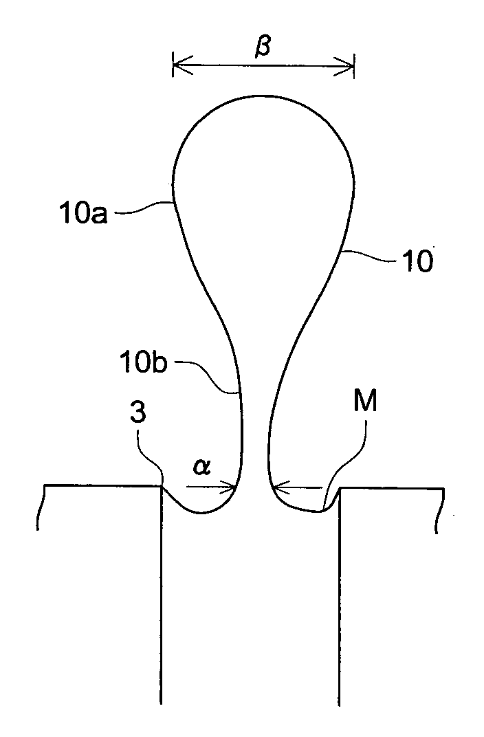
[0110] We tested by using a shear mode print head of 180 dpi as a nozzle pitch and 15 pl as the quantity of droplet to be jetted, driving the print head by a DRR waveform having a voltage ratio of |a| / |b|=2 / 1 (Draw and Reinforce voltage ratio), jetting droplets while fixing the “on” time of the first step (Draw) to 1 AL and changing the “on” time of the second step (Reinforce), observing and calculating the ratio of α / β (where α(μm) is the diameter (μm) of the liquid on the front end of the jetting side of the nozzle orifice and β(μm) is the maximum diameter (μm) of the ink pillar at the recovery position of the meniscus M), and inspecting the droplet tail curves of the jetted droplets.

[0111] Measurement of the ink pillar diameter: Made stroboscopic shoots of droplets that are jetted from nozzle orifices by a CCD camera and measured the diameters of ink pillars.

[0112] Inspection of droplet tail curves: Checked the droplet tail curves on the st...

Example

(COMPARATIVE EXAMPLE 1)

[0119] The same as those of Embodiments 1 to 3 except α / β is 1 / 2

[0120] Table 1 shows the result of tests of Embodiments 1 to 3 and Comparative example 1. TABLE 1α / βMeniscusTail curveComparative1 / 2Not on theCexample 1recoveryEmbodiment 11 / 3positionAEmbodiment 21 / 5AEmbodiment 3 1 / 10B

[0121] As for Comparative example 1 in Table 1, the α / β was greater than 1 / 3 and the droplet tail was curved.

[0122] As for Embodiments 1 and 2, α / β was equal to or smaller than 1 / 3 and the droplet tails have no curves. As for Embodiment 3, the droplet tail is too thin. The tail curve was a little corrected but still existed.

[0123] Judging from the above, we found that the preferable α / β value is

1 / 10<α / β≦1 / 3

Example

[0124] (Embodiment 4 to Embodiment 7)

[0125] We evaluated jetting stabilities and fast driving abilities of these embodiments by changing the Draw-Reinforce voltage ratio (|a| / |b|) of the DRR square wave under conditions of Embodiment 1.

[0126] We jetted each droplet at a speed of 8 m / s and inspected the stability of each droplet by the following evaluation standard:

[0127] A: Droplets were jetted steadily.

[0128] B: Droplets were jetted almost steadily with some fluctuation in the speed but without any jetting failure.

[0129] C: Droplets were jetted but their speeds were not constant and some jetting failures occurred.

[0130] We evaluated the fast driving abilities of the embodiments by the length of the driving period.

[0131] Table 2 shows the result of the evaluations. TABLE 2Embodi-Embodi-Embodi-Embodi-ment 4ment 5ment 6ment 7α / β1 / 5|a| / |b|1 / 11.5 / 12 / 13 / 1Tail curveNoneNoneNoneNoneJettingBAABstabilityTime beforet1 > t2 > t3 > t4α / β = 1 / 5

[0132] The above embodiments all had the α / β...


PUM


Abstract

A method of driving a droplet jetting head comprising nozzle orifices to jet droplets, pressure generating chambers each of which can store liquid and communicate with one of the orifices, and pressurizing devices to change the pressures of the pressure generating chambers, comprising the steps of increasing the pressure in the pressure generating chamber by the pressurizing device and protruding liquid in the pressure generating chamber from the nozzle orifice as a droplet, and separating the liquid which protrudes from the nozzle orifice when α/β is equal to or less than 1/3 where α(μm) is the diameter (in micrometers) of an liquid pillar (protruded from the nozzle orifice) at the front end of the nozzle orifice and β(μm) is the maximum diameter (in micrometers) of the liquid pillar.

Description

BACKGROUND OF THE INVENTION [0001] 1. Field of the Invention [0002] This invention relates to a method of driving a droplet jetting head that jets droplets from orifices. More particularly, this invention relates to a method of driving a droplet jetting head that can suppress curvature of the tail of a droplet jetted from a nozzle orifice and improve the accuracy of landing of a droplet. [0003] 2. Description of Related Art [0004] A droplet jetting head like an inkjet print head that jets droplets from nozzle orifices to record images with micro ink droplets jets a droplet by generating a pressure in a pressure chamber to land in a recording medium such as recording paper and the like. [0005] There have been various devices to give a pressure to a pressure chamber. The droplet jetting head to be explained here has a pressure chamber surrounded with walls of piezoelectric element and jets an ink droplet through a nozzle orifice by deforming the piezoelectric element. The droplet jett...

Claims


Application Information

Patent Timeline
IPC IPC(8): B41J2/01B41J2/045B41J2/055B41J2/14
CPCB41J2/04516B41J2/04526B41J2/04573B41J2202/10B41J2/04588B41J2/14209B41J2/04581
Inventor NISHIWAKI, CHISEASANO, KAZUOKIKUKAWA, SHOZO
Owner KONICA MINOLTA INC
Features
  • R&D
  • Intellectual Property
  • Life Sciences
  • Materials
  • Tech Scout
  • Unparalleled Data Quality
  • Higher Quality Content
  • 60% Fewer Hallucinations
Learn More