
Electrical discharge catheter system for extracting emboli in endovascular interventions

a catheter system and endovascular technology, applied in the field of catheter systems and medical interventions, can solve the problems of high risk of embolism, frequent diffuse and elongated occlusion, and difficult medical interventions

Inactive Publication Date: 2004-01-20
SHADDUCK JOHN H
View PDF3 Cites 111 Cited by
  • Summary
  • Abstract
  • Description
  • Claims
  • Application Information

AI Technical Summary

Problems solved by technology

In such bypass grafts, the occlusions are frequently diffuse and elongate making medical interventions problematic.
It has been found that conventional treatments of such saphenous vein bypass grafts (e.g., balloon angioplasty, atherectomy, etc.) can cause significant risk of embolisms by dislodging occlusive material that can then migrate downstream.
If an embolism occurs at a critical location in the patient's circulatory system, a permanent injury or even death may occur.
The risk of embolism also is prevalent in medical interventions to treat occlusions in native vessels.
For example, it is known that stent deployment often leads to the dislodgement of embolic fragments.
In some occlusions in native vessels, such as the carotid arteries, the risks of emboli reaching the brain are so significant that catheter-based treatments of such occlusions are rarely practiced.
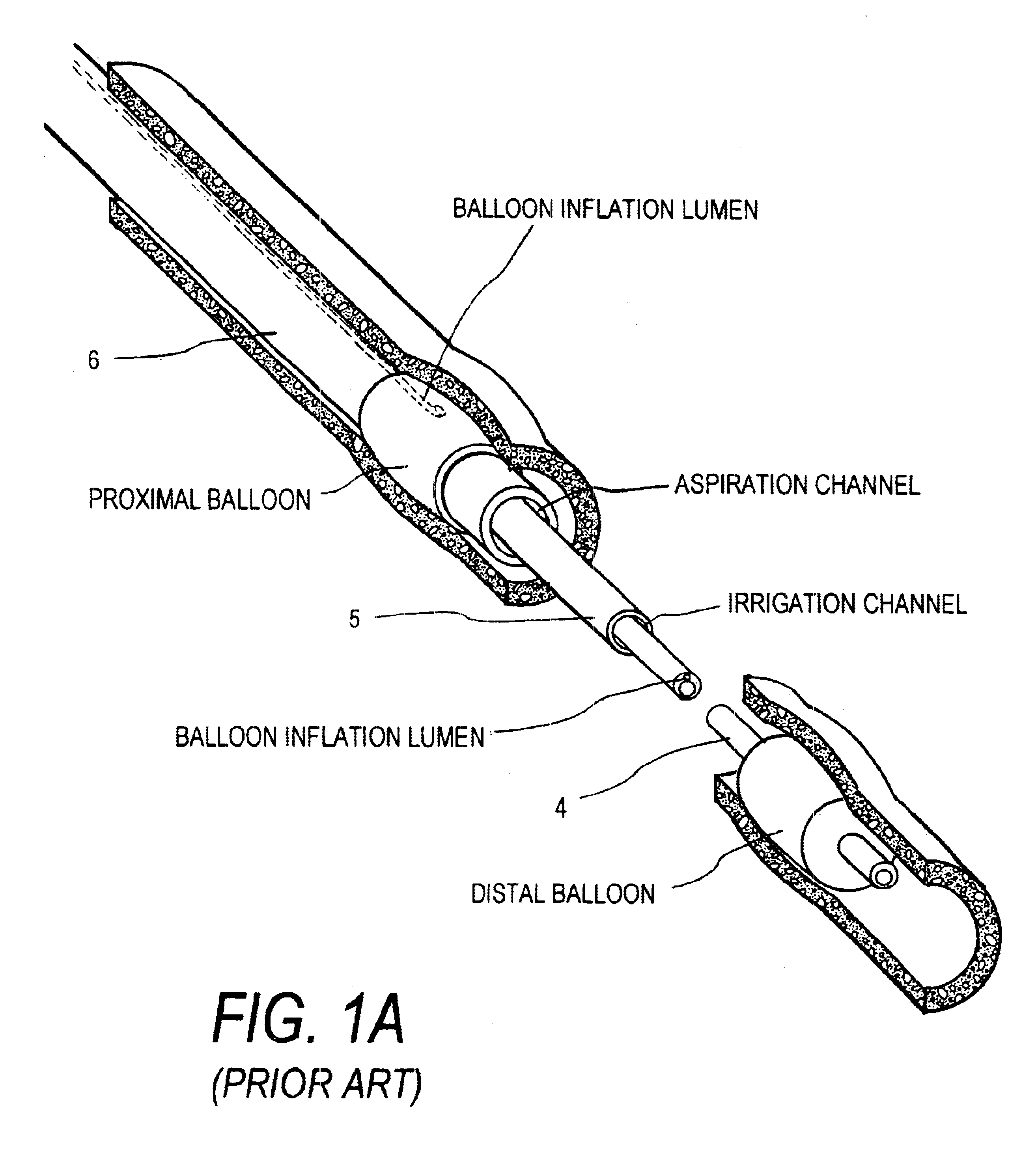
Such treatments may dislodge emboli between the upstream and downstream balloons.
The principal difficulty in designing an interventional catheter system for controlling emboli in vascular grafts relates to the small size of a typical bypass graft.
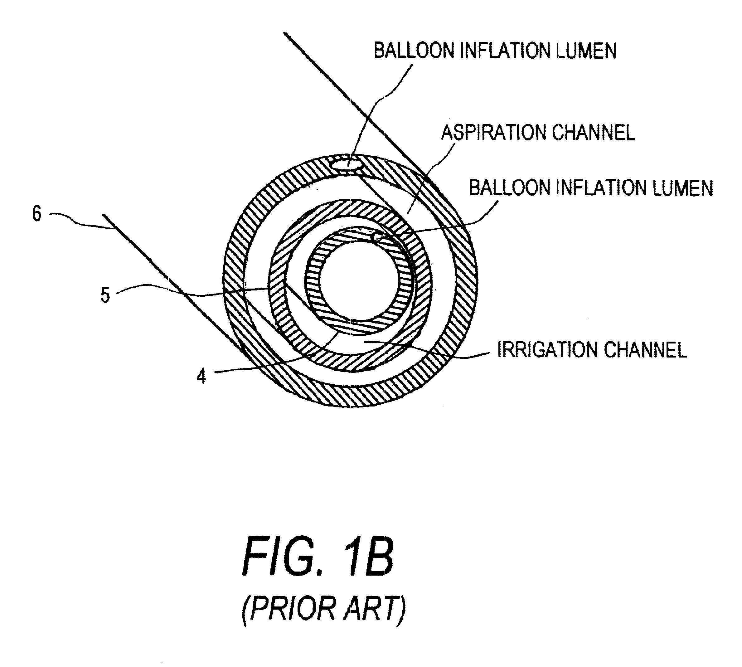
As one can easily understand, it is problematic to construct a catheter assembly that has an outer diameter of significantly less than about 3 mm. and still provide an inner lumen diameter of 600 .mu.m or more for extracting emboli--particularly when the catheter will require as many as four other inflow / outflow channels or lumens.
This open dimension of the working space on one side of the catheter may be too small to carry large embolic fragments to the open end of the aspiration passageway.
Besides the fact that a 2.8 mm. catheter assembly of FIG. 1A cannot optimize dimensions for (i) the working space, (ii) the irrigation pathway, and (iii) the emboli aspiration pathway, there are several other technical reasons that limit the suitability of such a catheter assembly for containing and removing emboli.
If the aspiration channel were suddenly blocked, significant overpressures would instantly build up in the working space.
As can be understood from FIGS. 1A-1B, even slight changes in the crosssections of the irrigation and aspiration pathways will make it difficult to modulate pressures to maintain the looped circulatory flow at a particular pressure.
More likely, there will be pressure spikes in the working space that could risk rupturing the vessel and risk the patient's health.
A third serious drawback of the catheter assembly of FIG. 1A relates to its lack of flexibility.
Due to the limited treatment time in which fluid flows about the working space (i.e., as little as 2 to 4 minutes since downstream blood flow is blocked by the balloon) there probably will be inadequate time to adjust the catheter in some way to insure that fluid flows reach all wall portions of the vessel.
However, it would very difficult to carry blood through three different catheter sleeves and then around the paired occlusion balloons.
Any such perfusion functionality would likely require a much larger assembly cross-section, which is not a realistic option.

Method used


Image

  • Electrical discharge catheter system for extracting emboli in endovascular interventions
  • Electrical discharge catheter system for extracting emboli in endovascular interventions
  • Electrical discharge catheter system for extracting emboli in endovascular interventions

Examples


Embodiment Construction

I. Principles Relating to Extraction and Emulsification of Emboli Based on Pressure Differential

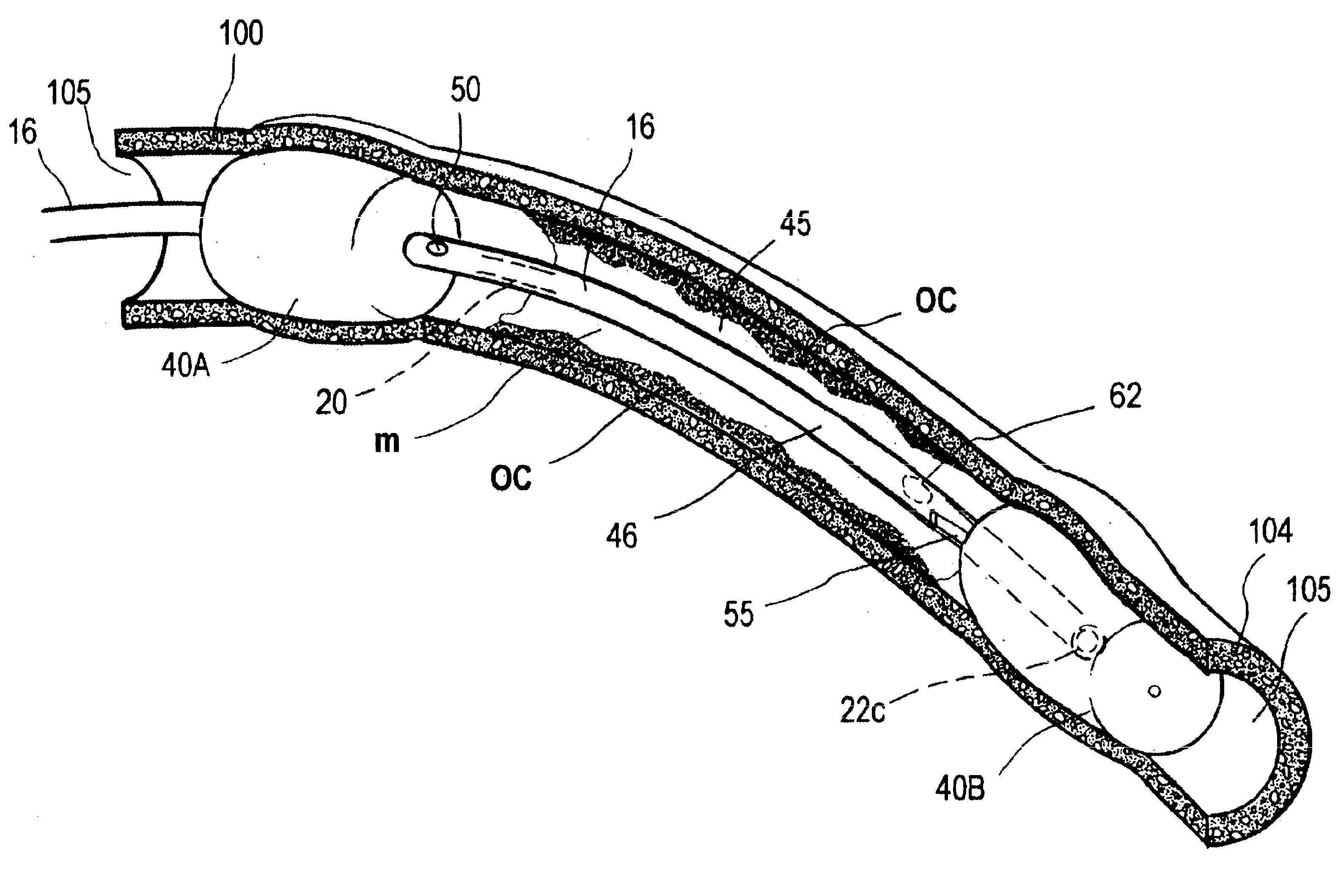
Daniel Bernoulli, an eighteenth-century Swiss scientist, discovered that as the velocity of a fluid in cases, its pressure decreases--often called Bemoulli's Law. The catheter system according to the present invention utilizes a micro-electrical discharge system for providing high repetition rate discharges in small channels (herein termed a microchannel structure) in a catheter working end to create high velocity fluid flows as a novel means of exploiting Bernoulli's Law for medical therapeutic purposes. The high velocity fluid flows created by the invention, together with selected levels of turbulence generated by such fluid flows, are adapted for use in catheter based medical interventions in a very small endoluminal working spaces. More in particular, the invention utilizes a sequence of electrical discharges for the purposes of: (i) creating a pressure differential to draw a fluid th...


PUM


Abstract

A catheter system for removing occlusive materials from a targeted endoluminal site, such as a vascular graft. The catheter system utilizes an electrical source and a controller to deliver sequences of very small electrical discharges between paired electrodes in a fluid-jet arrangement (i) to cause high fluid flow velocities in the catheter's fluid extraction pathway based on Bernoulli's Law of Pressure Differential, (ii) to create a selected level of turbulent fluid flows within the targeted site to remove occlusive material from the vessel walls and to thereafter suction fluids and entrained embolic particles into the extraction pathway, and (iii) to emulsify any embolic particles having a cross-sectional dimension larger than a couple of hundred micrometers to allows passage of the embolic particles through the elongate catheter to the catheter handle.

Description

1. Field of the InventionThe present invention relates to medical devices and techniques, and more particularly to catheter systems and medical interventions for treating elongate occluded regions in vascular coronary artery grafts. The inventive catheter system is adapted for capturing and extracting embolic fragments that typically develop in any endovascular intervention. The catheter system utilizes sequences of micro-electrical discharges in catheter channels to (i) remove occlusive materials from the vessel walls around a treatment site; (ii) generate fluid extraction forces; and (iii) to emulsify or ablate large fragments of dislodged occlusive materials, thus allowing the emboli extraction system to be fabricated in a very small diameter catheter.2. Description of Related ArtVascular grafts in coronary artery bypass procedures (CABG) often become occluded over time by plaque, thrombus, or other deposits that can significantly reduce blood flow through the graft. In such bypa...

Claims


Application Information

Patent Timeline
Patent Type & Authority Patents(United States)
IPC IPC(8): A61B17/22A61B17/32
CPCA61B17/22022A61B17/3203A61B2017/22051A61B2017/22067A61B2017/32032
Inventor SHADDUCK, JOHN H.
Owner SHADDUCK JOHN H
Learn More