Protective acoustic cover assembly

a technology of acoustic cover and assembly, which is applied in the direction of electrical transducers, casings/cabinets/drawers, casings/cabinets/drawers details, etc., can solve the problems of not protecting the acoustic transducer from incidental exposure to liquids (e.g., spills, rain, etc., and tight pore structures

Active Publication Date: 2005-04-14
WL GORE & ASSOC INC
View PDF25 Cites 117 Cited by
  • Summary
  • Abstract
  • Description
  • Claims
  • Application Information

AI Technical Summary

Benefits of technology

[0030] (b) mounting the protective acoustic cover assembly adjacent the aperture to protect the acoustic transducer from particulates and liquid ingress.

Problems solved by technology

Acoustic transducers are easily susceptible to being physically damaged, so they are often mounted in a protective housing with apertures located over the position of the acoustic transducer.
These apertures, however, do not protect the acoustic transducer from incidental exposure to liquids (e.g., spills, rain, etc.) or fine dust and other particulate.
Because it has a non-uniform behavior with frequency, materials that are highly reactive are typically not selected for use as a protective acoustic cover, unless the application requires high environmental protection.
Non-porous materials or ones with very tight pore structures, however, tend to transmit sound via mechanical vibration of the material (i.e. reactance), as opposed to physically passing air particles through the pores.
These thin, low mass materials, however, can be more delicate, less durable, and more difficult to handle during fabrication and subsequent installation into an electronic device, so very low reactance may not be achievable in practice.
The fact that the properties of acoustic resistance, acoustic reactance, durability, manufacturability, and contamination protection are often competing have made it difficult to develop protective acoustic materials that simultaneously meet aggressive acoustic and liquid and particulate protection targets.
However, although this laminated covering system may be effective in preventing liquid entry into an electronic device, the lamination results in an excessively high specific acoustic impedance (dominated by reactance) which is unacceptable in modern communication electronics where sound quality is a critical requirement.
The membrane effectively restricts liquid passage through the membrane but also results in a high specific acoustic impedance.
Additionally, the patent fails to specifically teach the material parameters of the membrane that are required in order to achieve low specific acoustic impedance, although it does generally describe the parameters in terms of porosity and air permeability.
As previously discussed, although a non-porous film can provide excellent liquid protection, such a non-porous film suffers from extremely high specific acoustic impedance, which is dominated by reactance.
This can produce sound that is excessively muffled and distorted.
Although such a construction may have been effective for its intended use in rugged military-type field telephone sets, it is not desirable for use in modern communication electronic devices because the reactance is extremely high.
This is because the two stainless steel disks physically constrain the membrane, limiting its ability to vibrate.
Additionally, sintered metal disks are relatively thick and heavy and are thus impractical for lightweight, handheld portable electronic devices.
However, although this construction reduces the reactance of the laminate comparatively, the degree of specific acoustic reactance still remains quite high.
Although the prior art mentioned above primarily discusses highly reactive materials, most commercially available protective cover materials are typically resistive.
These physical material properties create higher viscous losses associated with the air particles passing through the pores.
Because highly resistive materials are often highly undesirable in many applications, materials of this type can be produced with lower specific acoustic resistance, but this is usually accomplished by increasing the pore size of the material.
This results in a decrease in the level of liquid and particulate protection.

Method used


Image

  • Protective acoustic cover assembly
  • Protective acoustic cover assembly
  • Protective acoustic cover assembly

Examples


example 1

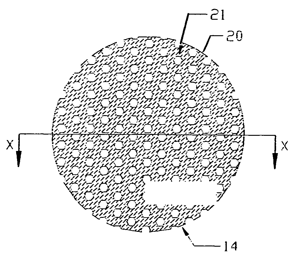
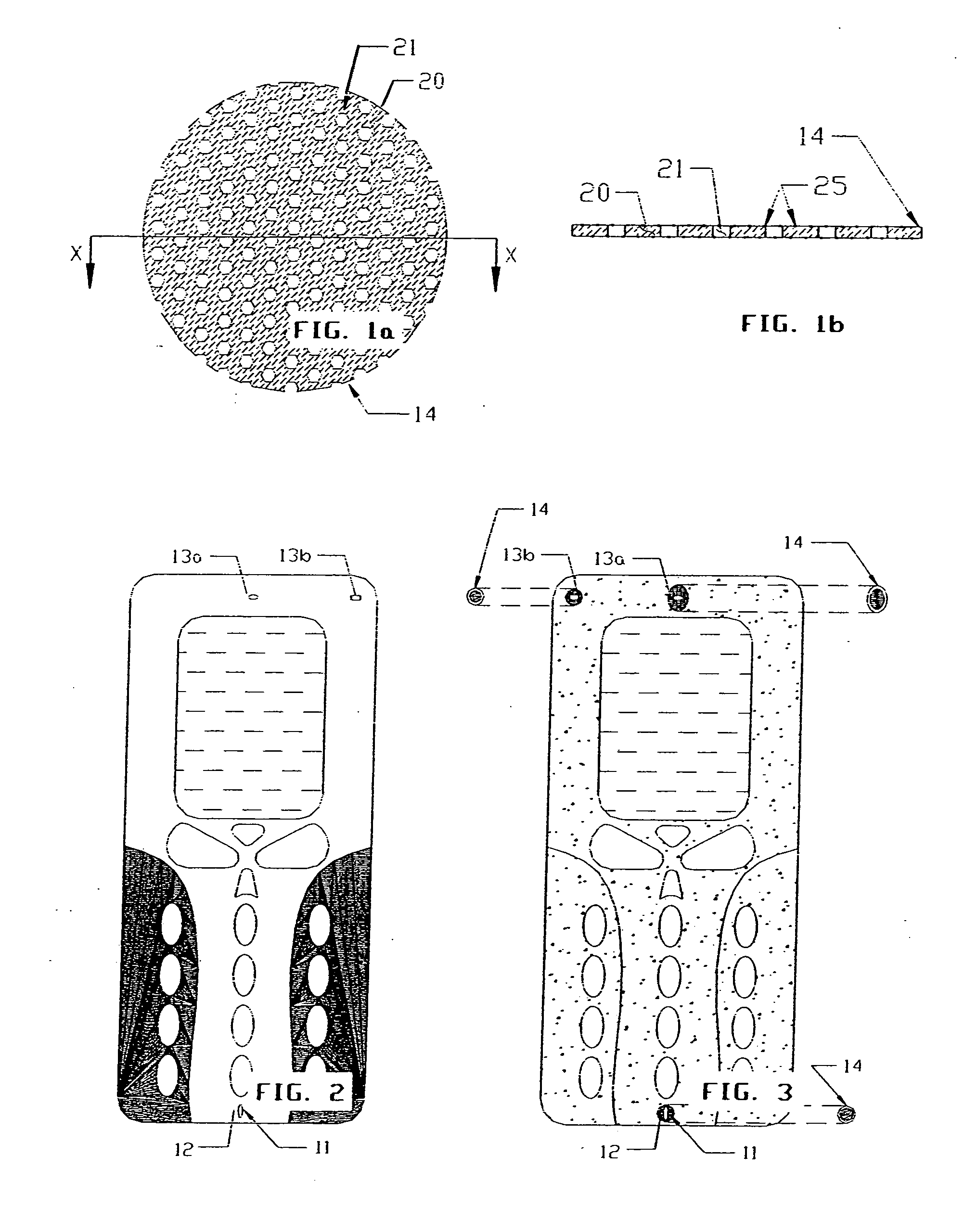
[0077] Hydrophobic Perforated Nickel Foil

[0078] A perforated nickel foil material manufactured by Stork Veco B.V. was provided comprising the following nominal properties: thickness—0.0005″ (12 micrometers); average maximum pore size—87 micrometers; percent open area—45%. A disc, 35 mm diameter, was cut from the material. A treatment was prepared using Teflon AF fluoropolymer from DuPont. The treatment consisted of 0.15% by weight of the Teflon AF in 99.85% by weight solvent, which was TF5070 from 3M. An adequate amount of coating solution was poured into a petri dish and the sample was fully immersed using tweezers. The sample was subsequently suspended in a fume hood for approximately 10 minutes. Specific acoustic resistance and reactance, along with I-WEP were tested according to the test methods outlined above. A comparison of the results from these tests are shown in Table 1 along with the material properties of thickness, and average maximum pore size.


PUM


Abstract

A protective acoustic cover assembly including a metal foil with perforations, and a treatment on one or more surfaces of said metal foil. The treatment is a hydrophobic or oleophobic treatment, or both. The protective acoustic cover assembly has an average specific acoustic resistance of less than about 11 Rayls MKS from 250-300 Hz, an average specific acoustic reactance magnitude of less than about 1 Rayls MKS from 250-300 Hz, and an instantaneous water entry pressure value of greater than about 11 cm. The perforations of the metal foil preferably have an average maximum pore size of less than about 150 micrometers. The protective acoustic cover assembly further includes an adhesive mounting system, and the preferred metal foil is nickel.

Description

FIELD OF THE INVENTION [0001] The present invention generally relates to a material providing environmental protection for an acoustic transducer (such as a microphone, ringer or speaker) employed in an electronic device. More specifically, the present invention relates to a protective acoustic cover assembly comprising a treated perforated metal foil that has low acoustic impedance, occupies limited space and has the ability to withstand exposure to dust and liquid intrusion. BACKGROUND OF THE INVENTION [0002] Most modern electronic devices, such as radios and cellular telephones, contain at least one acoustic transducer (e.g. microphone, ringer, speaker, buzzer, etc.). An acoustic transducer is an electrical component that converts electrical signals into sound, or vice-versa. Acoustic transducers are easily susceptible to being physically damaged, so they are often mounted in a protective housing with apertures located over the position of the acoustic transducer. These apertures...

Claims


Application Information

Patent Timeline
Patent Type & Authority Applications(United States)
IPC IPC(8): H04M1/20H04M9/08H04RH04R1/02H04R25/00H05K5/00H05K5/03
CPCH04R1/086H04R1/023H05K5/03
Inventor BANTER, CHAD A.REIS, BRADLEY E.
Owner WL GORE & ASSOC INC
Why Eureka
Try Eureka