
Illuminating device for vehicle

Inactive Publication Date: 2005-03-31
TOYODA GOSEI CO LTD
View PDF8 Cites 31 Cited by
  • Summary
  • Abstract
  • Description
  • Claims
  • Application Information

AI Technical Summary

Benefits of technology

[0008] Accordingly, it is an objective of the present invention to provide an illuminating device for vehicles capable of effectively illuminating a road surface section beside a vehicle body. It is another objective of the present invention to provide a simply configured illuminating device for vehicles.

Problems solved by technology

This restricts the illuminated range, regardless of the relatively large number of the bulbs.
Further, the device does not illuminate a road surface section below the front side door sufficiently.
Further, like the device of the other publication, the light of the bulb is radiated substantially vertical from the light exiting opening to the road surface, restricting the illuminated area.
In addition, the bulb installed in the rear side molding and the light passage defined in the front side molding complicate the configuration of the illuminating device.
Further, the light radiated by the aforementioned devices, which proceeds substantially vertical toward the target road surface, may be interfered by an outer side surface of the front or rear side door.

Method used


Image

  • Illuminating device for vehicle
  • Illuminating device for vehicle
  • Illuminating device for vehicle

Examples


first embodiment

[0020] the present invention will be described with reference to FIGS. 1 to 4.

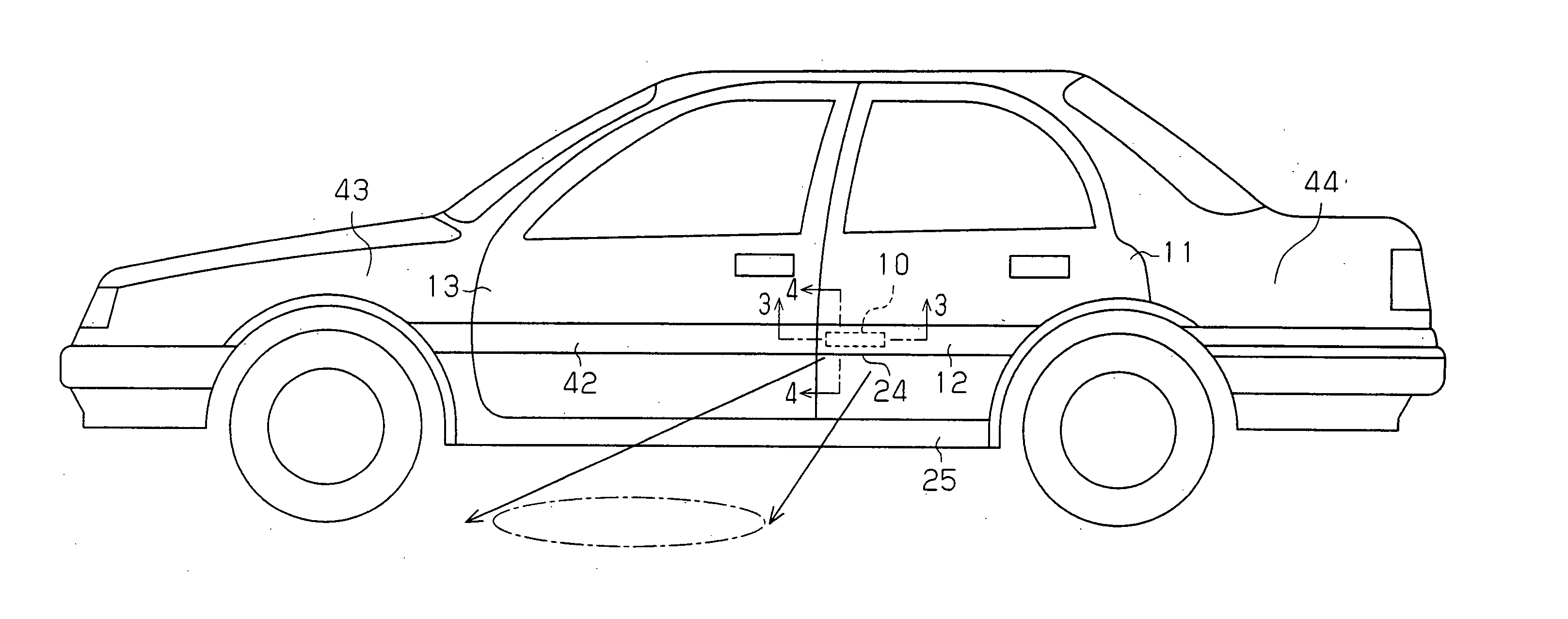
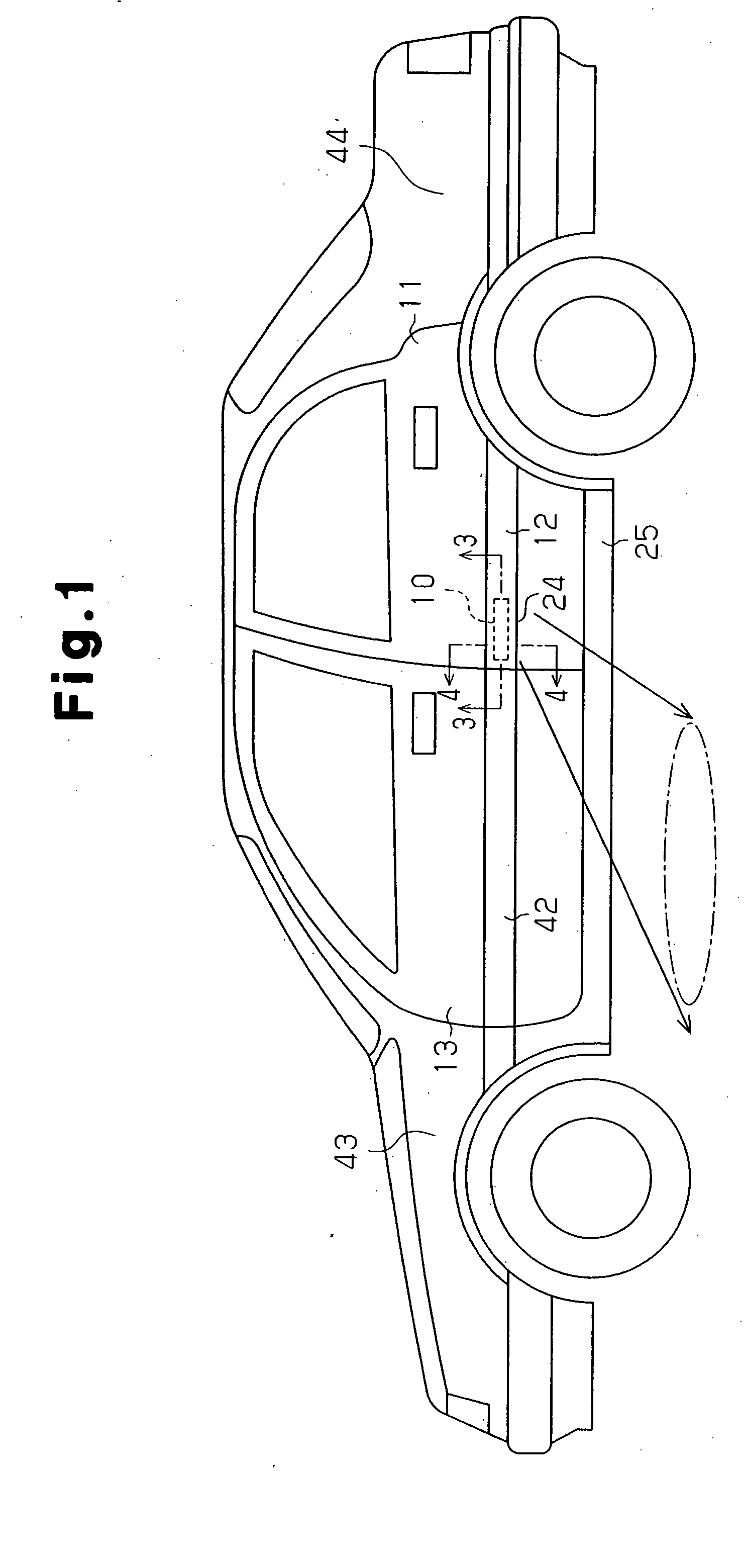
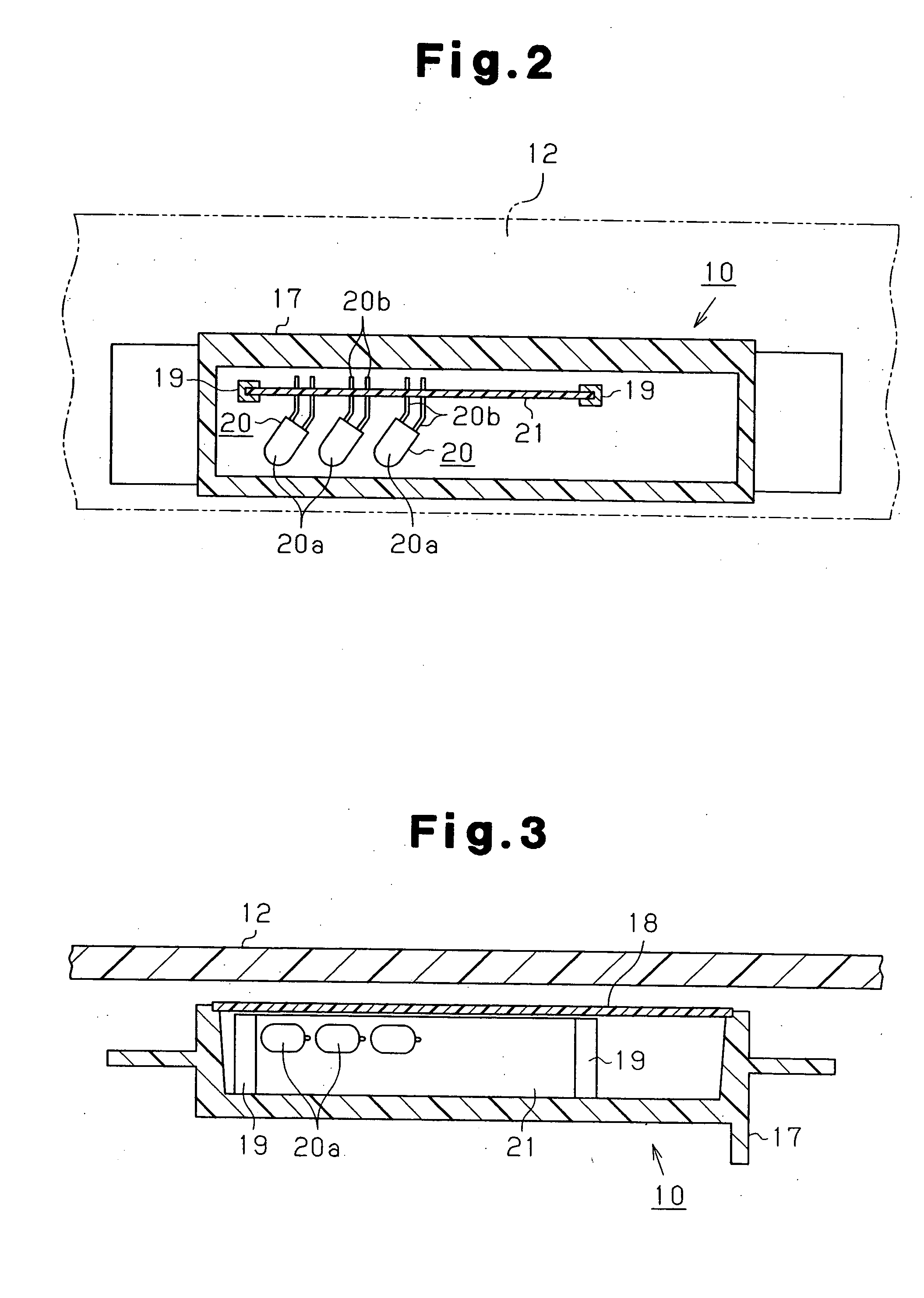
[0021] As illustrated in FIG. 1, an illuminating device 10 is installed in a side door of a vehicle body, or, more specifically, attached to an outer side surface of a rear side door 11. The illuminating device 10 is installed in a band-like protection molding 12 (a rear side molding 12), which is attached to a lower section of the outer side surface of the rear side door 11. More specifically, the illuminating device 10 is located at a vertical middle section of the rear side molding 12. The device 10 radiates the light along the optical path indicated by the arrows in FIG. 1, thus illuminating a road surface section beside a front side door 13. A front side molding 42, which corresponds to the rear side molding 12, is attached to an outer side surface of the front side door 13.

[0022] The rear side molding 12 is formed of synthetic resin, such as polypropylene or polyurethane, and extends in the fore-and...


PUM


Abstract

An illuminating device is installed at an outer side surface of a rear side door of a vehicle for illuminating a road surface section beside a front side door of the vehicle. The device is accommodated in a rear side molding secured to the outer side surface of the rear side door. The light source of the illuminating device radiates light along a linear optical path extending diagonally downward from a portion of the outer side surface of the rear side door in which the light source is installed to the road surface section beside the front side door. Further, the illuminating device includes a prism lens for refracting the light of the light source outwardly and away from the outer side surface of the vehicle body. This enables the device to effectively illuminate the road surface section beside the vehicle.

Description

BACKGROUND OF THE INVENTION [0001] The present invention relates to illuminating devices used in vehicles for, for example, allowing a driver or passenger to enter or exit a passenger compartment easily in the dark. [0002] Conventionally, the techniques described in Japanese Laid-Open Utility Model Publication Nos. 62-145843 and 1-158254 are known as the aforementioned illuminating devices. In the device of the publication No. 62-145843, a light introducing board having a narrow, elongated plate-like shape is disposed in a molding of a vehicle's rear side door (a rear side molding). An installing hole extends through a middle section of the light introducing board and receives four bulbs (lamps) and a reflecting mirror. Further, a light transmitting window is formed at a lower end of the rear side molding, extending in the longitudinal direction of the rear side molding. The light of the bulbs is converged and diffused by the reflecting mirror and transmitted through the light trans...

Claims


Application Information

Patent Timeline
IPC IPC(8): B60Q1/32F21S8/10F21V5/02
CPCB60Q1/323F21Y2101/02F21V5/02F21S48/1225F21Y2115/10F21S41/285B60Q1/247
Inventor TAKEDA, KAZUOADACHI, TAKAOOHBA, TATSUYANAWASHIRO, MITSUHIROKAWASHIMA, DAIICHIRO
Owner TOYODA GOSEI CO LTD
Learn More