Fan mounting means and method of making the same

a technology of mounting means and fan arrangement, which is applied in the direction of motors, applications, household objects, etc., can solve the problems of threading/assembling, complex and laborious manufacturing of belts, etc., and achieve the effect of quick, reliable and economical manufacturing

Inactive Publication Date: 2005-03-31
EBM PAPST ST GEORGEN & -
View PDF6 Cites 147 Cited by
  • Summary
  • Abstract
  • Description
  • Claims
  • Application Information

AI Technical Summary

Benefits of technology

[0006] Another advantageous feature of the invention is the method of making the membrane, namely by placing a mold radially between the fan housing and mounting frame, and injection-molding the elastomeric interconnecting membrane. With such a method, a membrane can be quickly, reliably, and economically manufactured from an elastomeric material. It is also advantageous to make the fan housing and mounting frame from a hard plastic by injection molding.

Problems solved by technology

Such vibrations result from the normal operation of the fan and from changes in load and rotation speed.
This solution has the disadvantage that the belts are complex and laborious to manufacture, and to thread / assemble, after their manufacture.

Method used


Image

  • Fan mounting means and method of making the same
  • Fan mounting means and method of making the same
  • Fan mounting means and method of making the same

Examples


Embodiment Construction

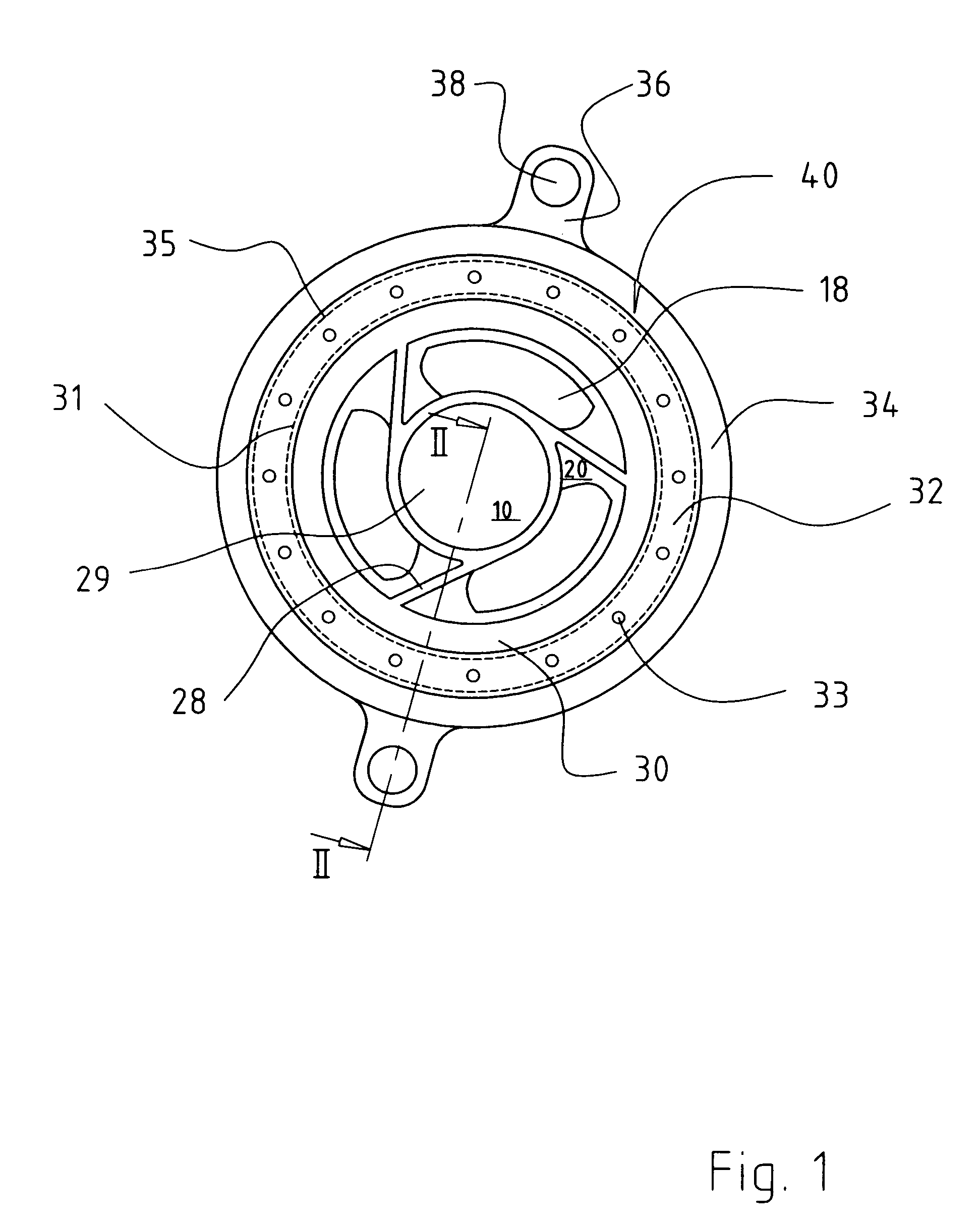
[0017]FIG. 1 is a plan view of a first exemplary embodiment of a fan arrangement 40 according to the present invention having a fan 10, viewed in a direction indicated by arrow I of FIG. 2.

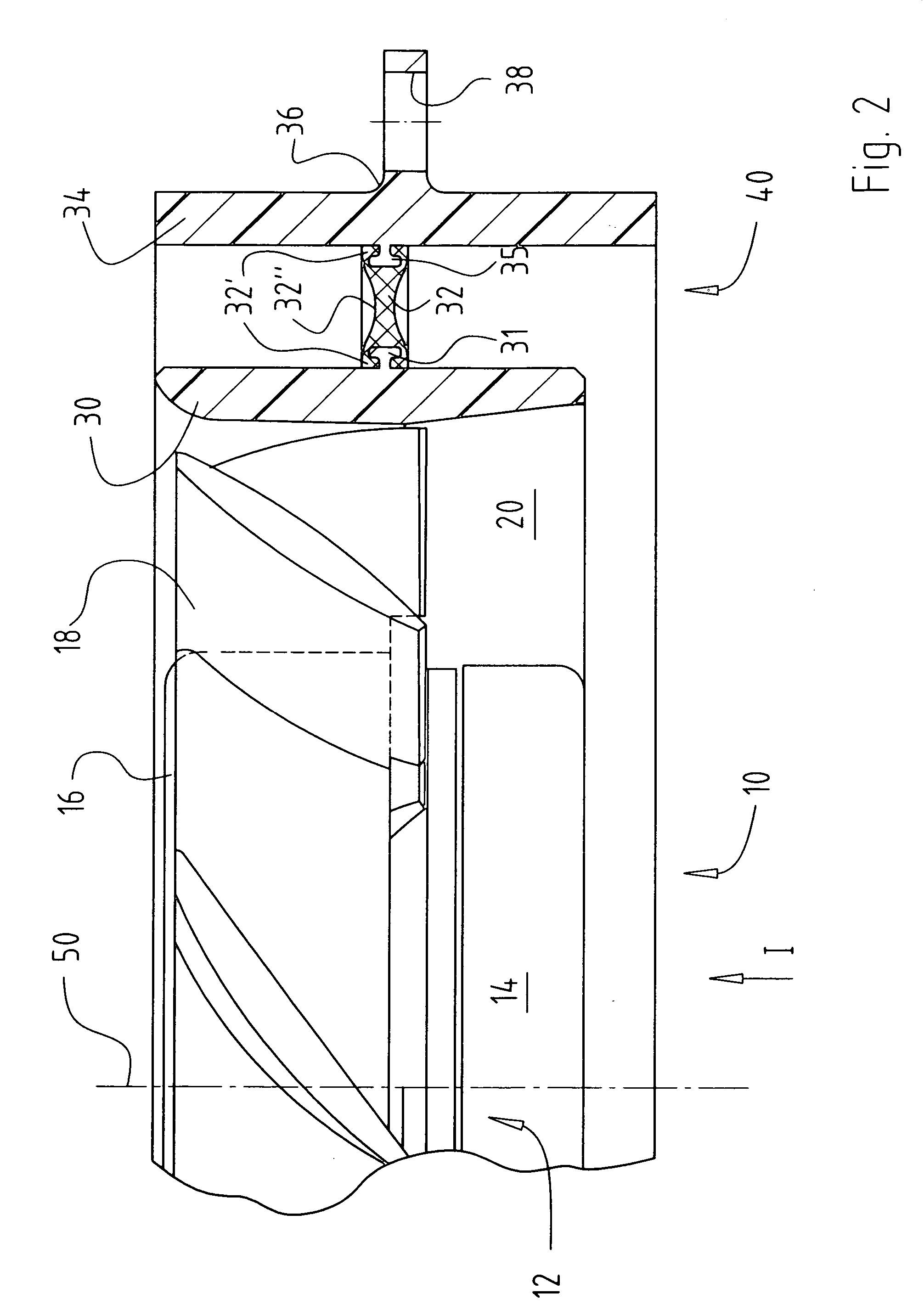
[0018]FIG. 2 is a side view of fan arrangement 40, viewed in section along line II-II of FIG. 1.

[0019] Fan 10 has an electric motor 12 comprising a stator arrangement 14 and a rotor 16, also fan blades 18, struts 28, a motor retention flange 29 (see FIG. 3), and a fan housing 30 comprising a lateral projection 31. The rotation axis of the fan is labeled 50 in FIG. 2.

[0020] Fan arrangement 40 has a membrane or diaphragm 32 comprising a plurality of apertures (through holes) 33, as well as a mounting frame 34 comprising a projection 35, a mounting frame holder 36, and a mounting opening 38.

[0021] Stator 14 is connected via struts 28 to fan housing 30, and drives rotor 16. Motion is thereby imparted to fan blades18, and an air stream flows through region 20 between fan housing 30 and stator 14. A...


PUM

PropertyMeasurementUnit
elasticaaaaaaaaaa
circumferenceaaaaaaaaaa
thicknessaaaaaaaaaa

Abstract

A fan arrangement comprises a fan (10) having a fan housing (30) within which is arranged a blower wheel (18) which, in operation, moves air from an intake side of the fan (10) to a delivery side. Arranged radially outside the fan housing (30) is a surrounding mounting frame (34) that serves to support the fan housing (30). A membrane (32), made of an elastic material, elastically connects the fan housing (30) and mounting frame (34) to one another and is formed with through holes or apertures (33) that, in the event of a closure of the output or delivery side of the fan arrangement (40), enable a return flow, from the delivery side to the intake side of the fan arrangement (40), of air moved by the blower wheel (18).

Description

FIELD OF THE INVENTION [0001] The present invention relates generally to an improved vibration-damping fan arrangement, and to a method of making the fan arrangement. BACKGROUND [0002] In numerous applications, for example ventilation of a vehicle seat or of equipment units, the vibrations produced by a fan are perceived as obtrusive. Such vibrations result from the normal operation of the fan and from changes in load and rotation speed. These vibrations tend to be transferred from the fan to the entire apparatus in which the fan is located. [0003] DE 196 43 760 C1 and corresponding U.S. Pat. No. 6,050,890, BAYER+ / DAIMLER / CHRYSLER disclose a fan arrangement in which a fan is suspended within flexible belts. This solution has the disadvantage that the belts are complex and laborious to manufacture, and to thread / assemble, after their manufacture. SUMMARY OF THE INVENTION [0004] It is therefore the object of the invention to provide a novel fan arrangement and a method of manufacturin...

Claims


Application Information

Patent Timeline
Patent Type & Authority Applications(United States)
IPC IPC(8): B29C45/00B29C45/16F04D29/02F04D29/64F04D29/66F16F15/08
CPCB29C45/0062B29C45/1676B29L2031/08B29L2031/445F16F15/08F04D29/023F04D29/646F04D29/668F04D25/0613F05D2300/43
Inventor WINKLER, WOLFGANG ARNOMETZGER, PETER
Owner EBM PAPST ST GEORGEN & -
Why Eureka
Try Eureka