
Small hole electrical discharge machining method and small hole electrical discharge machining apparatus and electrode inserting method and electrode inserting apparatus

a technology of electrical discharge and machining method, which is applied in the direction of electrical-based machining electrodes, vibration holders, manufacturing tools, etc., can solve the problems of difficult to perform long-term stable electrode feeding, and clogged or plugged electrode guides

Active Publication Date: 2005-04-14
ELENIX KK
View PDF11 Cites 18 Cited by
  • Summary
  • Abstract
  • Description
  • Claims
  • Application Information

AI Technical Summary

Benefits of technology

[0010] To attain the above object, A small hole electric discharge machining method using a small hole electrical discharge machining apparatus having electrode holding means for holding an upper part of an electrode and electrode guide means for guiding a lower part of the electrode, the electrode being fed t...

Problems solved by technology

However, in the conventional small hole electrical discharge machining method and apparatus, dirty water from a worked portion enters an interior of the electrode guide, thereby the electrode guide got clogged or plugged.
Hence, it is difficult to perform a long-term stable electrode feeding, and therefore continuous working was limited to one performed for approximately 2 hours or to one wherein the number of the worked holes was 1,000 pieces or so.
Resultantly, a hole of the electrode guide became small in diameter, and therefore, it is difficult to perform long-term stable electrode feeding.
Also, the conventional electrode inserting step inserting the electrode into the electrode guide, it is difficult to insert the electrode having a very small diameter such as 0.01 mm, 0.02 mm, and 0.03 mm.

Method used


Image

  • Small hole electrical discharge machining method and small hole electrical discharge machining apparatus and electrode inserting method and electrode inserting apparatus
  • Small hole electrical discharge machining method and small hole electrical discharge machining apparatus and electrode inserting method and electrode inserting apparatus
  • Small hole electrical discharge machining method and small hole electrical discharge machining apparatus and electrode inserting method and electrode inserting apparatus

Examples


Embodiment Construction

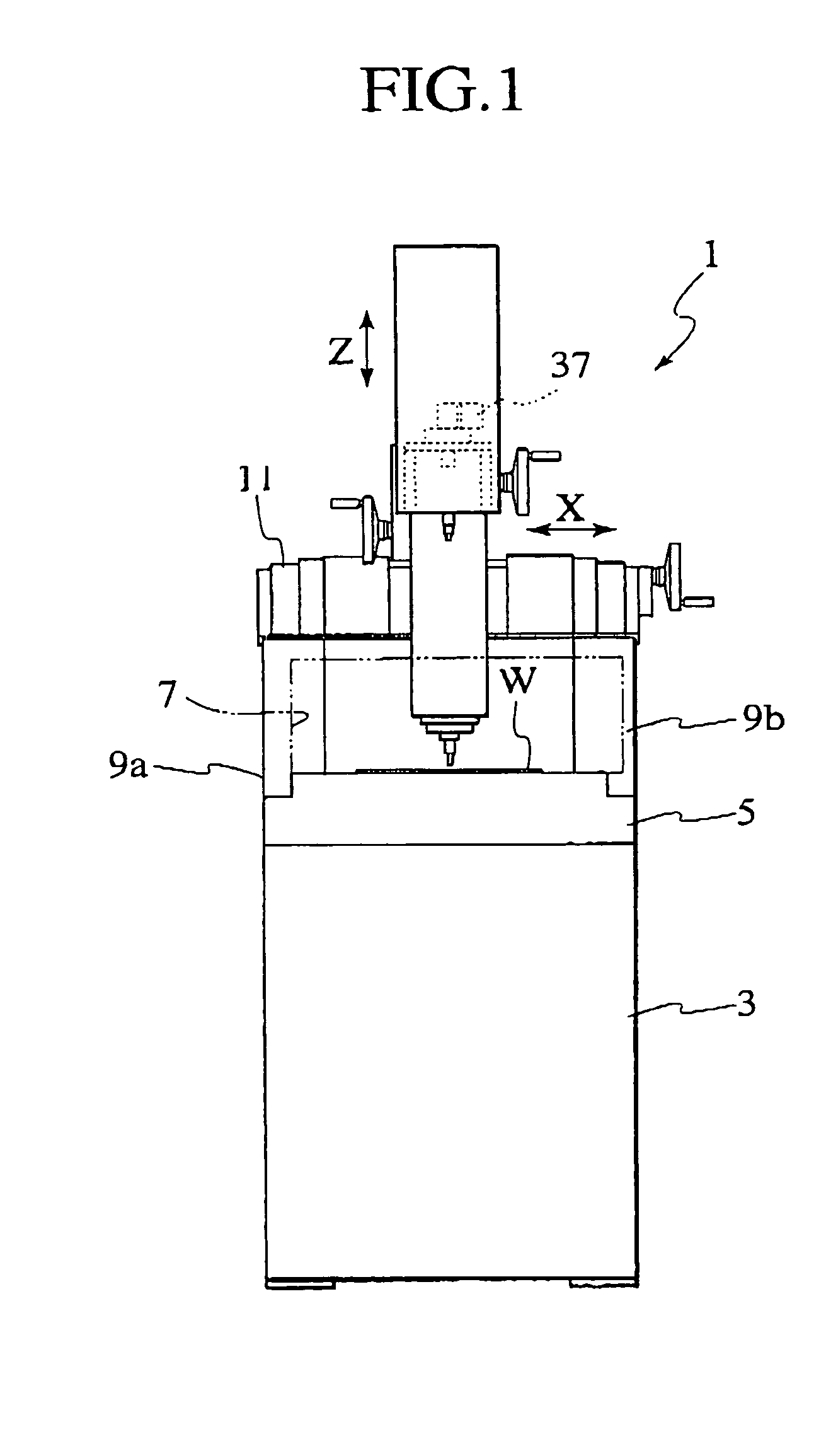
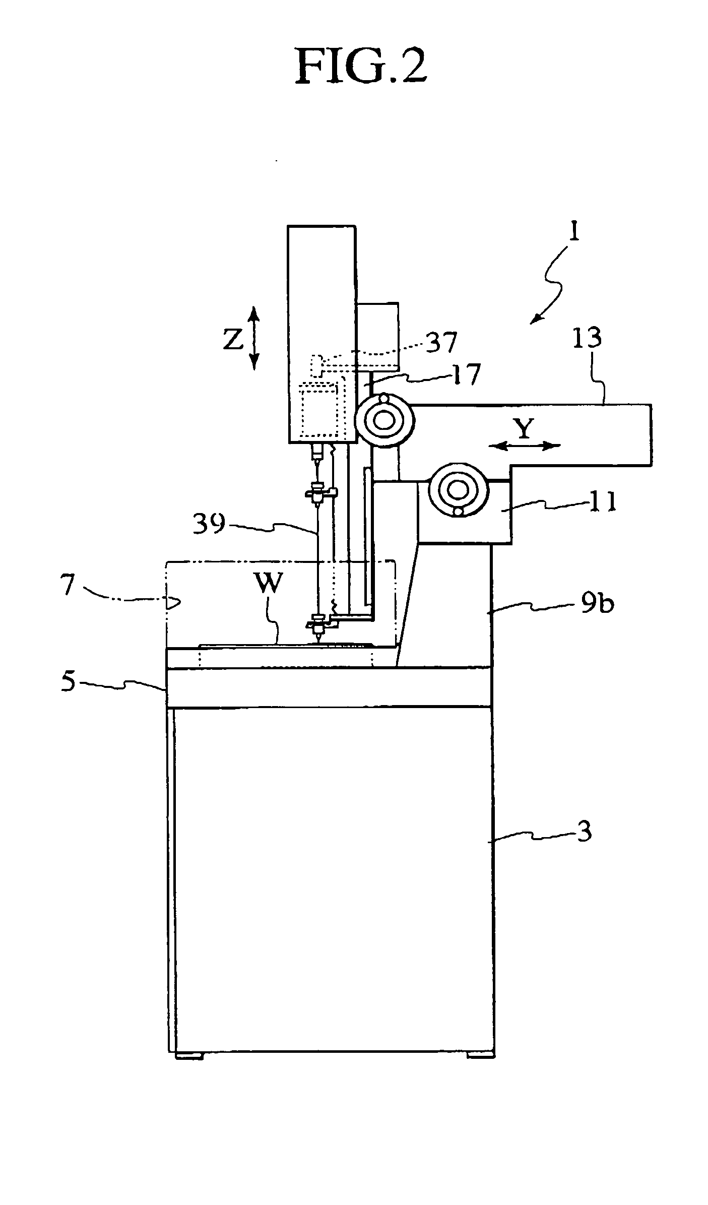
[0018] An embodiment of the present invention will hereafter be explained with reference to FIGS. 1 to 7.

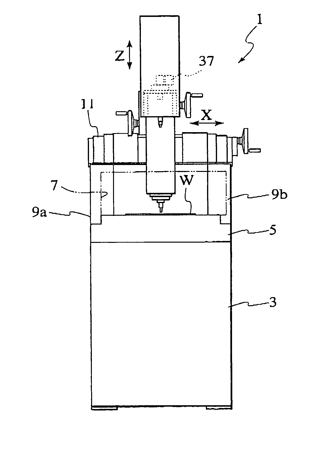
[0019] A small hole electrical discharge machining apparatus 1 according to the present invention comprises a pedestal 3, a work table 5 fixing a workpiece W and provided on the pedestal 3, and a work tank 7 provided on the work table 5 for containing the workpiece W. Also, at the rear (on the right side of FIG. 2) of the work table 5, columns 9a and 9b upwardly extending from the work table 5 are provided.

[0020] On the columns 9a and 9b, an X-axial carriage 11 that can be freely moved and positioned in X directions (see FIG. 1) is provided. On the X-axial carriage 11, a Y-axial carriage 13 that can be freely moved and positioned in Y directions intersecting the X directions is provided.

[0021] Referring to FIG. 3, on the front end (the left side end portion in FIG. 2) of the Y-axial carriage 13, a slide base 17 is attached, and the slide base 17 is configured to freely move in...


PUM

PropertyMeasurementUnit
Poweraaaaaaaaaa
Conductionaaaaaaaaaa

Abstract

A small hole electrical discharge machining apparatus 1 is comprised of electrode holding 27 means for holding an upper part of an electrode 39, electrode guide means 41 for guiding a lower part of the electrode 39, a jet nozzle 73 injecting a water let (WJ) from the electrode holding means 27, and a fluid channel 97 which supplies a gas, such as air, to an electrode guide 75 of the electrode guide means. The electrode 39 is guided with the water jet (WJ) toward the workpiece (W), and small hole electrical discharge machining is performed while the gas is being released from the electrode guide 75 into a working liquid via the fluid channel 97.

Description

BACKGROUND OF THE INVENTION [0001] 1. Field of the Invention [0002] The present invention relates to a small hole electrical discharge machining method and a small hole electrical discharge machining apparatus, and an electrode inserting method with respect to an electrode guide of the small hole electrical discharge machining apparatus and an electrode inserting apparatus. [0003] 2. Description of the Related Art [0004] In a conventional small hole electrical discharge machining apparatus, a stick-shaped, or pipe-shaped, slender electrode is rotatably supported by a main-axis portion. The main-axis portion is moved up / down by a feed screw that is rotated by a main-axis feed motor. By doing so, a lower end portion of the electrode is caused to come near to a workpiece and electrical discharge is caused to occur from the electrode. Thereby, a small hole is drilled. Then, an electrode guide member guides the lower end portion of the electrode to a proper accurate position. [0005] Also...

Claims


Application Information

Patent Timeline
IPC IPC(8): B23H1/10B23H7/26B23H7/36B23H9/14
CPCB23H1/10B23H9/14B23H7/36B23H7/265
Inventor YOKOMICHI, SHIGEHARU
Owner ELENIX KK
Learn More