Eureka AIR delivers breakthrough ideas for toughest innovation challenges, trusted by R&D personnel around the world.

Method and apparatus for thermal development

a technology of thermal development and photosensitive elements, which is applied in the direction of diffusion transfer processes, instruments, photosensitive materials, etc., can solve the problems of time-consuming, difficult to maintain the cleanliness and operation of the processor, and the mess within the processor

Inactive Publication Date: 2005-04-21
EI DU PONT DE NEMOURS & CO
View PDF10 Cites 22 Cited by
  • Summary
  • Abstract
  • Description
  • Claims
  • Application Information

AI Technical Summary

Benefits of technology

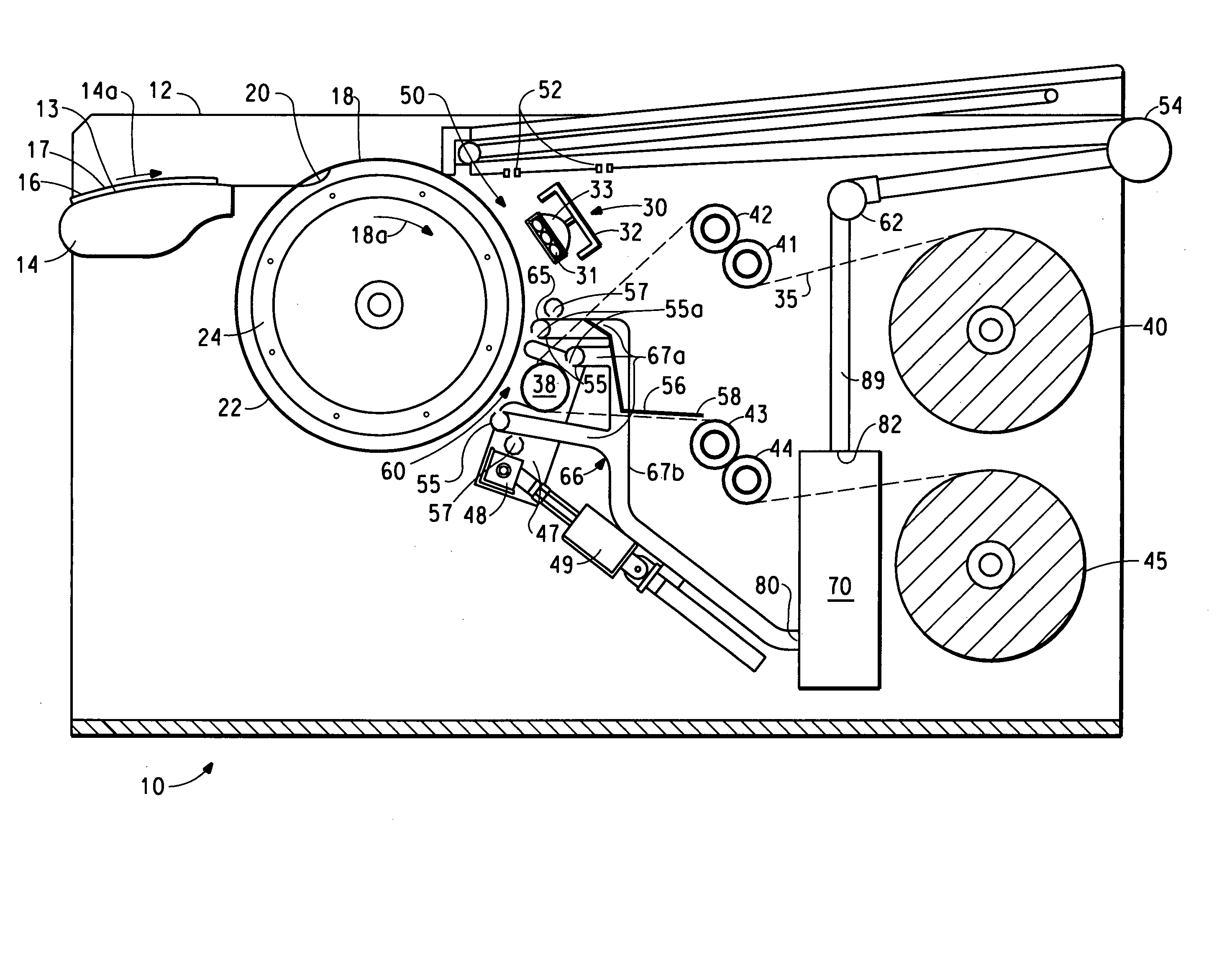
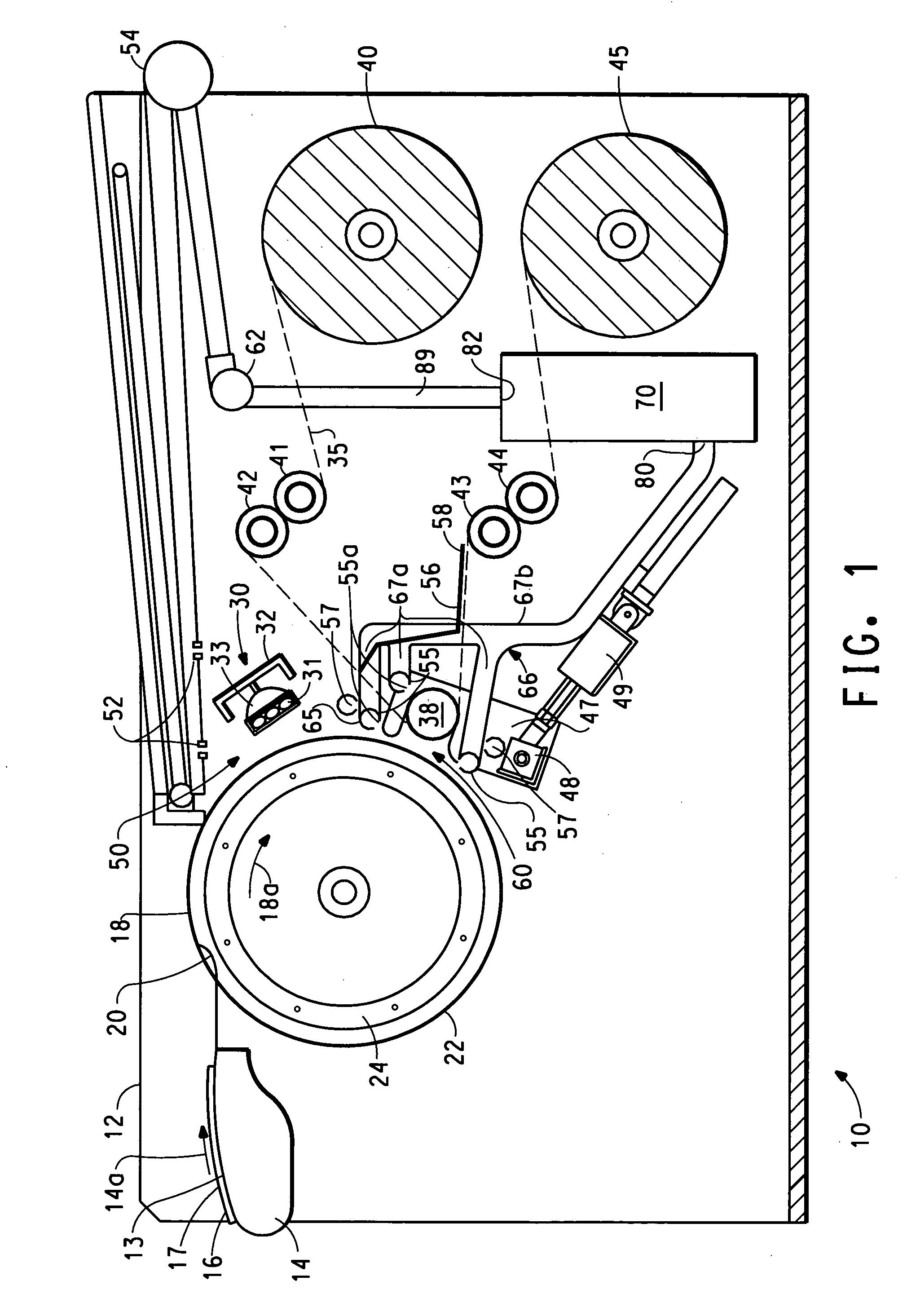
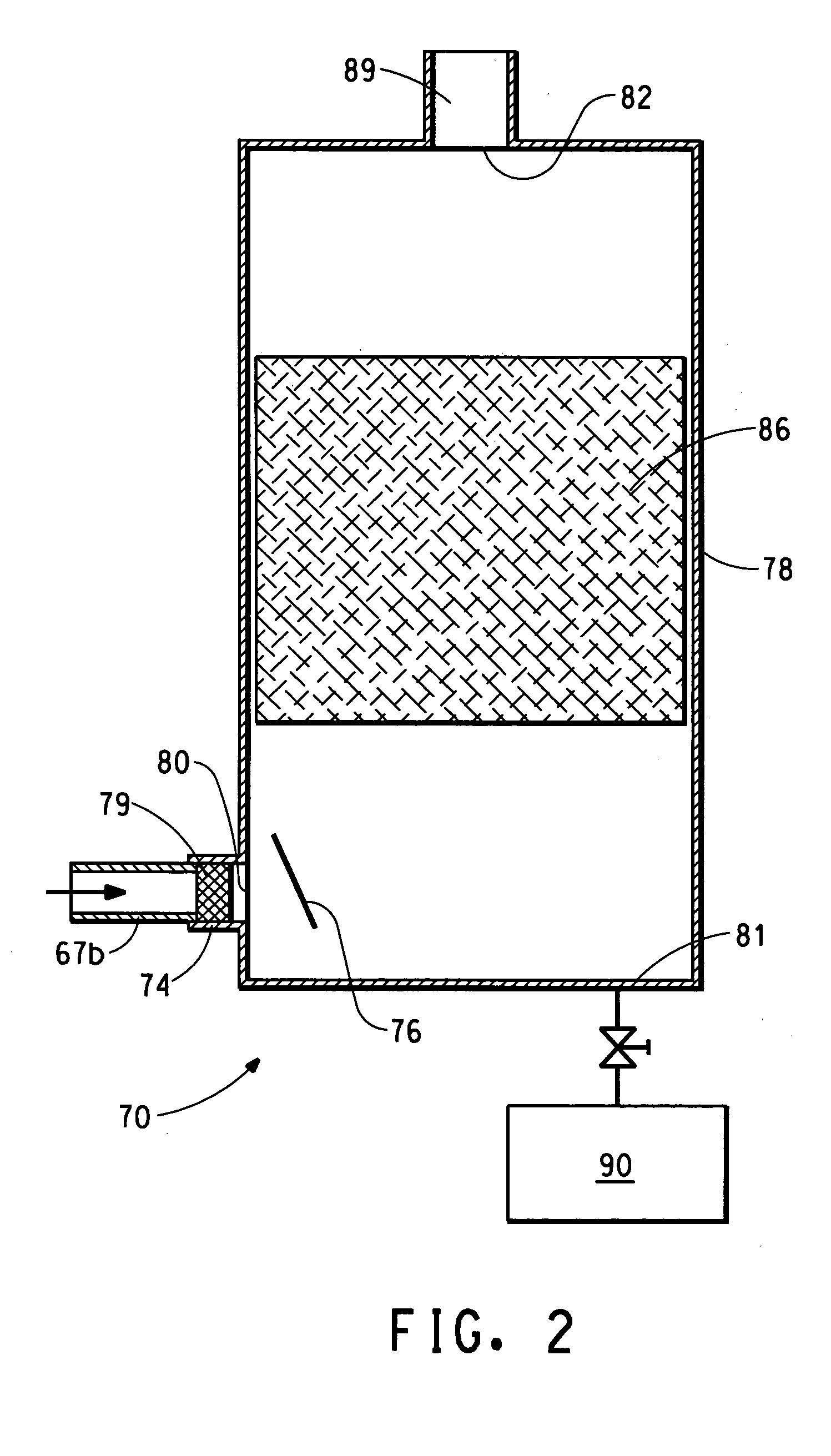
[0013] The present invention provides a method for forming a relief pattern from a photosensitive element containing a composition layer having an exterior surface and capable of being partially liquefied. The method comprises heating the exterior surface of the composition layer at a heating station to a temperature Tr sufficient to cause a portion of the layer to liquefy and cause one or more components in the layer to form a vapor, and collecting the vapor at the heating station.
[00...

Problems solved by technology

However, developing systems that treat the element with a solution are time consuming since drying for an extended period (0.5 to 24 hours) is necessary to remove absorbed developer solution.
The vapor can condense within a thermal development processor and drip uncontrolled onto different areas of the processor creating a mess within the processor.
Thus, the vapor and / or condensate from the vapor that remain inside the processor make it difficult to maintain the cleanliness and operation of the processor, and ultimately can damage the thermal development apparatus.
Also, the photosensitive elements that are being developed in the processor can be damaged by the condensate, particularly when the condensate drips onto an image area of the element.
Condensate dripping onto these areas causes disturbances in the surface of the element that can render the surface unsuitable for printing.
The patent indicates that certain compositions emit fumes during heat processing and are less suitable.
However, the patent did not address the problem of emitted fumes during heat processing.
However, the vapor has a tendency to condense prior to reaching the pan, causing dripping inside the unit.
This approach however limits the photosensitive elements that can be thermally processed and thus restricts the customer in the types of plates that can be made.
So a problem arises during thermal development of photosensitive elements in that vapor and condensate from the vapor are generated.
Exhaust systems in thermal development processors in the prior art either do not address the problem or have only limited success in managing the vapor and condensate in the processor.
The uncontrolled presence of the vapor and / or condensate can make maintaining the cleanliness and the operation of the processor difficult, and can ultimately result in damaging the thermal development processor.
Also, uncontrolled dripping of the condensate in the processor can damage the photosensitive element to the extent that it cannot be used for printing.

Method used


Image

  • Method and apparatus for thermal development
  • Method and apparatus for thermal development
  • Method and apparatus for thermal development

Examples


Embodiment Construction

)

[0017] The present invention is an apparatus and process for thermally developing a photosensitive element containing a composition layer capable of being partially liquefied, preferably to form a flexographic printing form. The apparatus heats the composition layer to a temperature sufficient to melt at least a portion of the layer. In particular, the present invention relates to an apparatus and process for controlling vapor and / or condensate from the vapor that is generated during thermal development of the photosensitive element.

[0018] Thermal development heats the photosensitive element to a development temperature that causes uncured portions of the composition layer to liquefy, i.e., melt or soften or flow, and be carried away by contact with an absorbent material. Cured portions of the photosensitive layer have a higher melting temperature than the uncured portions and therefore do not melt, soften, or flow at the thermal development temperatures. Thermal development of ph...


PUM


Abstract

This invention pertains to a method and an apparatus for thermally developing a photosensitive element, and particularly to a method and apparatus for controlling vapor and condensate created during thermal treating of the photosensitive element.

Description

BACKGROUND OF THE INVENTION [0001] 1. Field of the Invention [0002] This invention pertains to a method and apparatus for thermally developing a photosensitive element, and particularly to a method and apparatus that controls vapors and / or condensate created during thermal treating of the photosensitive element. [0003] 2. Description of Related Art [0004] Flexographic printing plates are well known for use in printing surfaces which range from soft and easy to deform to relatively hard, such as packaging materials, e.g., cardboard, plastic films, aluminum foils, etc. Flexographic printing plates can be prepared from photosensitive elements containing photopolymerizable compositions, such as those described in U.S. Pat. Nos. 4,323,637 and 4,427,759. The photopolymerizable compositions generally comprise an elastomeric binder, at least one monomer and a photoinitiator. Photosensitive elements generally have a photopolymerizable layer interposed between a support and a coversheet or mu...

Claims


Application Information

Patent Timeline
IPC IPC(8): G03D13/00G03F7/36
CPCG03F7/36
Inventor HACKLER, MARK A.KANNURPATTI, ANANDKUMAR R.MCMILLEN, ROBERT A.SHAMLIN, WILFORDTAGGI, ARTHUR J.LAKE, JEFFREY ROBERTNEUFEGLISE, DAVID B.SCHESKE, SIEGFRIED R.
Owner EI DU PONT DE NEMOURS & CO
Why Eureka
Eureka Blog
Learn More