Electrical connector

Inactive Publication Date: 2005-04-21
TYCO ELECTRONICS JAPAN GK
View PDF6 Cites 15 Cited by
  • Summary
  • Abstract
  • Description
  • Claims
  • Application Information

AI Technical Summary

Benefits of technology

[0013] It is therefore an object of the present invention to provide an electrical connector wherein it is possible to perform an e

Problems solved by technology

Because electrical continuity checks are typically performed by a harness maker, an automobile maker using the electrical connector, or the like, the

Method used


Image

  • Electrical connector
  • Electrical connector
  • Electrical connector

Examples


Example

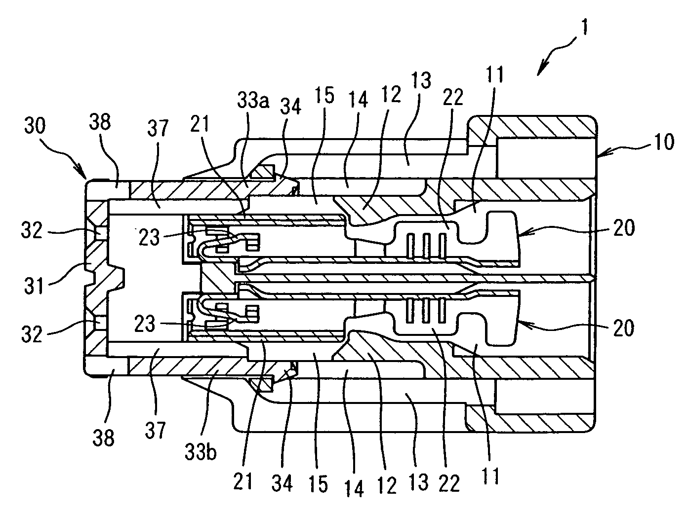
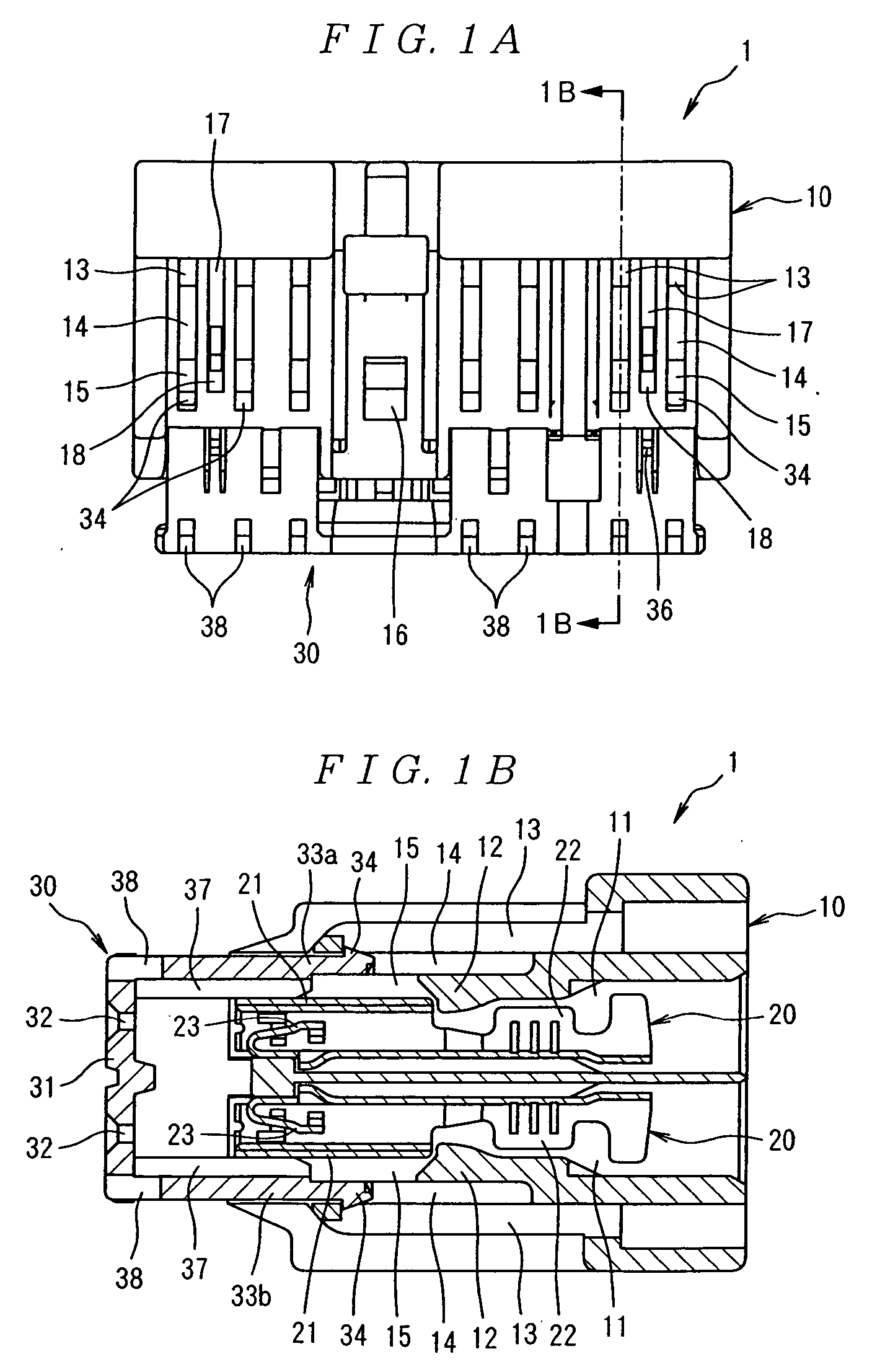
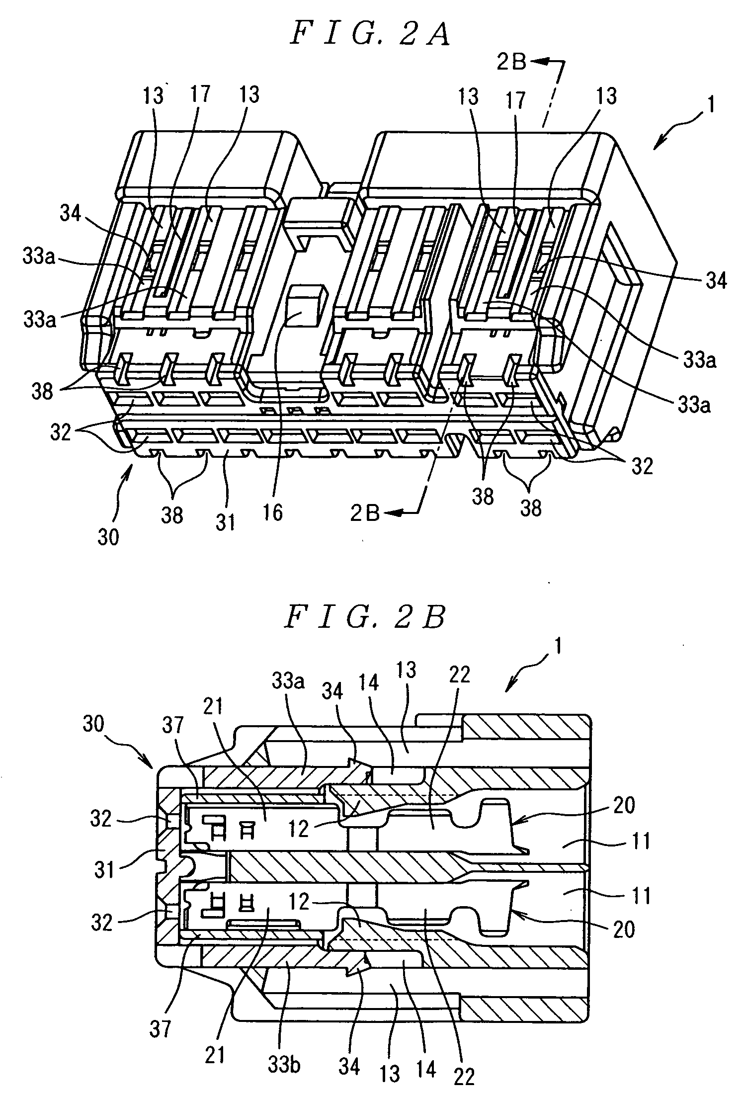
[0027]FIGS. 1A, 1B, 2A and 2B, show an electrical connector 1. As shown in FIGS. 1A-1B, the electrical connector 1 includes an insulating housing 10. The housing 10 has a substantially rectangular shape and is formed by molding a synthetic resin. A plurality of contact accommodating cavities 11 is formed in two rows (upper and lower rows) in a left-right direction (in the left-right direction in FIG. 1B) of the housing 10. As shown in FIGS. 3 and 5, each of the contact accommodating cavities 11 extends from a front side to a rear side of the housing. As shown in FIG. 1B, disposed in each of the contact accommodating cavities 11 is a locking arm 12. The locking arms 12 disposed in the upper rows of the contact accommodating cavities 11 extend forward at an inclination from a top wall of the housing 10. The locking arms 12 disposed in the lower rows of the contact accommodating cavities 11 extend forward at an inclination from a bottom wall of the housing 10.

[0028] As shown in FIGS. ...


PUM


Abstract

An electrical connector comprises an insulating housing having a plurality of contact accommodating cavities extending from a front side to a rear side of the housing. Each of the contact accomodating cavities has a first probe receiving opening formed adjacent thereto. A retainer that is moveable between a temporary locking position and a main locking position is attached to the front side of the housing. The contact accomodating cavities are accesible through the first probe receiving openings when the retainer is in the temporary locking position, and the contact accomodating cavities are accesible through second probe receiving openings formed in the retainer when the retainer is in the main locking position.

Description

FIELD OF THE INVENTION [0001] The invention relates to an electrical connector having a housing with contacts connected to electrical wires of a wire harness, for example, an automobile wire harness. BACKGROUND OF THE INVENTION [0002] A wire harness is constructed from numerous electrical wires, contacts, and the like. The contacts may be, for example, connected to the electrical wires of the wire harnesses and then arranged in a housing of an electrical connector. A locking arm may be disposed in the housing to secure the contacts and to prevent the contacts from slipping out of the housing. [0003] In order to prevent erroneous wiring of the wire harness and in order to prevent faulty connections between the contacts and the electrical wires, an electrical continuity check of the electrical connector is required. One example of an electrical continuity testing method is shown in FIGS. 11A, 11B, and 11C and is further illustrated in Japanese Patent Application Kokai No. 2000-182743....

Claims


Application Information

Patent Timeline
IPC IPC(8): H01R13/42H01R13/64H01R13/436
CPCH01R13/4365Y10S439/912H01R2201/20
Inventor SAGAWA, TETSUYAAITA, YASUMASAKAJII, TOMOAKISAWADA, RYO
Owner TYCO ELECTRONICS JAPAN GK
Why Eureka
Try Eureka