Coolant distribution interface for a battery module housing

a technology of cooling interface and battery module, which is applied in the direction of secondary cells, cell components, battery servicing/maintenance, etc., can solve the problems of shortened life of rechargeable batteries, deterioration of rechargeable batteries, and at least one battery module not generating the desired amount of power

Active Publication Date: 2020-09-17
SAMSUNG SDI CO LTD
View PDF0 Cites 1 Cited by
  • Summary
  • Abstract
  • Description
  • Claims
  • Application Information

AI Technical Summary

Benefits of technology

[0033]According to the coolant distribution interface of the present invention, it is possible to check in advance before the coolant leaks.

Problems solved by technology

If the heat emission / discharge / dissipation is not sufficiently performed, temperature deviations occur between respective battery cells, such that the at least one battery module cannot generate a desired amount of power.
In addition, an increase of the internal temperature can lead to abnormal reactions occurring therein and thus charging and discharging performance of the rechargeable deteriorates and the life-span of the rechargeable battery is shortened.
However, since liquid cooling media, such as water or alkanols, may conduct electricity, initiate corrosive processes or react with compounds of the battery cells located inside the battery module housing if coming into contact with them, this results in a high risk of leakage.
However, known technical solutions suffer from having a high number of interfaces in the cooling circuit.

Method used


Image

  • Coolant distribution interface for a battery module housing
  • Coolant distribution interface for a battery module housing
  • Coolant distribution interface for a battery module housing

Examples


Embodiment Construction

[0040]Reference will now be made in detail to embodiments, examples of which are illustrated in the accompanying drawings. Effects and features of the exemplary embodiments, and implementation methods thereof will be described with reference to the accompanying drawings. In the drawings, like reference numerals denote like elements, and redundant descriptions are omitted. As used herein, the term “and / or” includes any and all combinations of one or more of the associated listed items. Further, the use of “may” when describing embodiments of the present invention refers to “one or more embodiments of the present invention.”

[0041]In the drawings, the sizes of elements may be exaggerated for clarity. For example, in the drawings, the size or thickness of each element may be arbitrarily shown for illustrative purposes, and thus the embodiments of the present invention should not be construed as being limited thereto.

[0042]It will be understood that although the terms “first” and “second...


PUM

PropertyMeasurementUnit
pressureaaaaaaaaaa
chemicalaaaaaaaaaa
electrical energyaaaaaaaaaa

Abstract

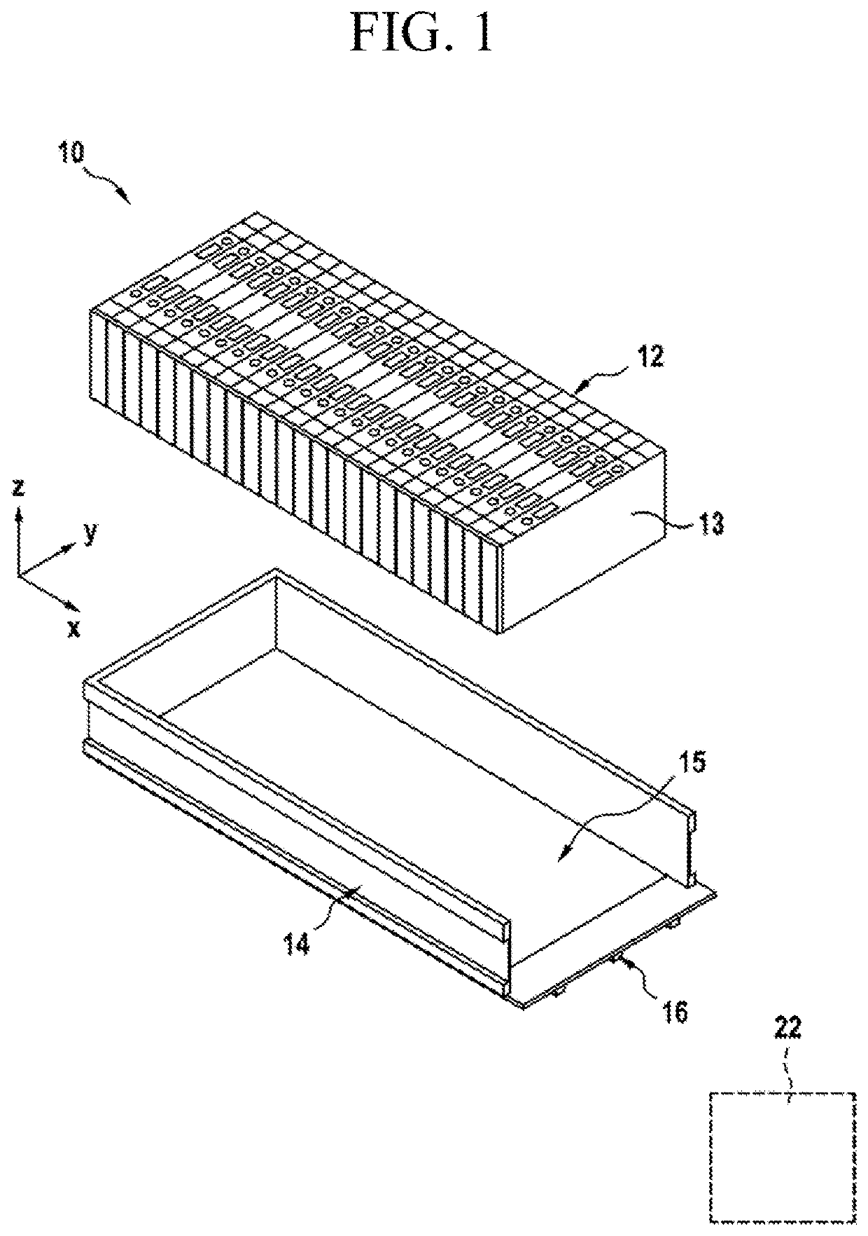
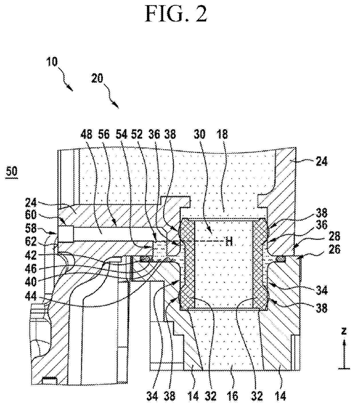
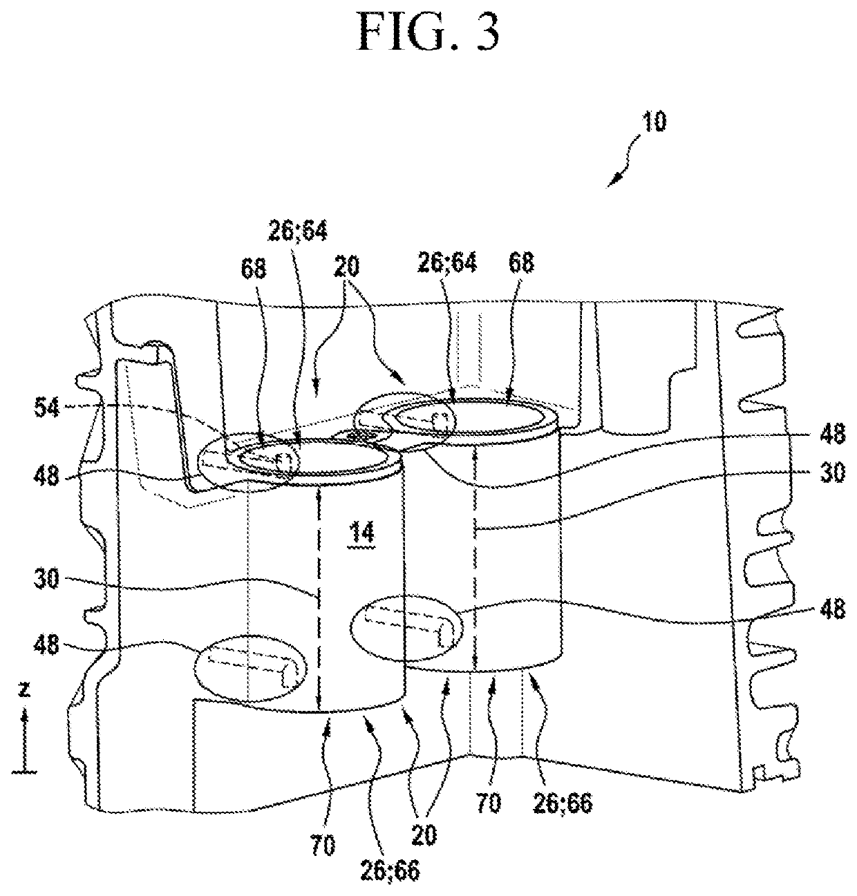
A coolant distribution interface for a battery system includes a battery module housing comprising a coolant channel, and at least one mounting portion located at an entrance of the coolant channel, wherein the mounting portion comprises a first sealing section and a second sealing section; a matching housing comprising a matching coolant channel, and at least one matching mounting portion located at an entrance of the matching coolant channel, wherein the matching mounting portion comprises a first matching sealing section and a second matching sealing section; a joint coolant channel configured to connect the coolant channel of the mounting portion and the matching coolant channel of the matching mounting portion; a shared sealing element locating between the second sealing section and the second matching sealing section; a channel sealing element sealing the first sealing section and first matching sealing section against the joint coolant channel; a security chamber configured to form by the mounting portion, the matching mounting portion, the shared sealing element and channel sealing element; and a testing channel connecting the security chamber with an outside of the battery module housing and the matching housing, wherein the test channel is penetrated at least one of the battery module housing and the matching housing.

Description

TECHNICAL FIELD[0001]The present invention relates to a coolant distribution interface, a battery system, wherein a cooling unit is connected to a battery module housing by the coolant distribution interface, further to a vehicle with the battery system and to a method of testing the leak tightness of the coolant distribution interface.BACKGROUND ART[0002]A rechargeable or secondary battery differs from a primary battery in that it can be repeatedly charged and discharged, while the latter provides only an irreversible conversion of chemical to electrical energy. Low-capacity rechargeable batteries are used as power supply for small electronic devices, such as cellular phones, notebook computers and camcorders, while high-capacity rechargeable batteries are used as the power supply for hybrid vehicles and the like.[0003]Rechargeable batteries may be used as a battery module formed of a plurality of unit battery cells coupled in series and / or in parallel so as to provide a high energ...

Claims


Application Information

Patent Timeline
Patent Type & Authority Applications(United States)
IPC IPC(8): H01M10/6567H01M10/625H01M10/42H01M2/10H01M50/209
CPCH01M2/1077H01M10/4228H01M10/625H01M10/6567H01M2220/20H01M10/6556H01M10/6568H01M10/613H01M50/209H01M10/63B60L58/26B60K6/28B60Y2200/92
Inventor RESEK, MATTHIASZAVCAR, GERNOT
Owner SAMSUNG SDI CO LTD
Why Eureka
Try Eureka