Disk conveying device and disk apparatus having the same

a technology of conveying device and disk, which is applied in the direction of information storage, instruments, data recording, etc., can solve the problems of difficult disadvantageous for realizing a compact design, and the required stroke of conveying disk is inevitably long, so as to reduce the depth size, and reduce the depth size of the disk apparatus used in the disk in the cartridge.

Inactive Publication Date: 2005-04-28
PANASONIC CORP
View PDF5 Cites 4 Cited by
  • Summary
  • Abstract
  • Description
  • Claims
  • Application Information

AI Technical Summary

Benefits of technology

[0029] Moreover, the disk conveying device can be applied, not only to a bare disk but also, to a disk in cartridge. And hence the depth size of the disk apparatus used in the disk in cartridge may be suppressed relatively small. In the disk in cartridge, in particular, since the window for recording and reproduction provided in the cartridge is opened to extend in the same direction as the disk conveying direction, the transfer direction of the optical head and the disk conveying direction must be matched, therefore, the depth size of the disk apparatus is generally increased in order to assure the transfer range of the optical head. But, by applying such disk conveying device, the depth size of the disk apparatus used in the disk in cartridge may be relatively suppressed small.
[0030] Further, the disk apparatus of the invention includes a disk conveying device of any one of the disk conveying devices described above, as a disk conveying device for conveying the disk as information recording medium between a first position outside of the disk apparatus and a second position inside of the disk apparatus, and hence the same effect as mentioned above can be obtained. That is, basically, the straight stroke of loading and unloading of disk can be shortened, and the depth size of the disk apparatus can be made compact. As a result, when the disk apparatus is used by incorporating integrally in a thin type image display device or the like, the assembling performance can be enhanced.

Problems solved by technology

In the conventional disk apparatus, however, the conveying device is designed to convey the disk in a straight stroke from the disk loading and unloading position outside of the disk apparatus to the recording and reproducing position inside of the disk apparatus by way of the disk access opening, and the required stroke of conveying the disk is inevitably long.
It is hence disadvantageous for realizing a compact design by reducing the depth size of the disk apparatus.
However, in the conventional structure, it is hard to reduce the depth size, and such demand cannot be satisfied.
In the cartridge such as DVD-RAM, generally, the cartridge inserting direction or cartridge holding position is specified, and it is difficult and strange for the user to insert the cartridge in a different direction from the specified ordinary inserting direction, and the operational performance of disk apparatus is spoiled.
However, in this case, the workability is poor when holding the bare disk or cartridge at the conveying device side (specifically on the disk tray), and the stability in conveying motion tends to be lower.

Method used


Image

  • Disk conveying device and disk apparatus having the same
  • Disk conveying device and disk apparatus having the same
  • Disk conveying device and disk apparatus having the same

Examples


Embodiment Construction

[0041] Preferred embodiments of the invention are specifically described below by referring to the accompanying drawings.

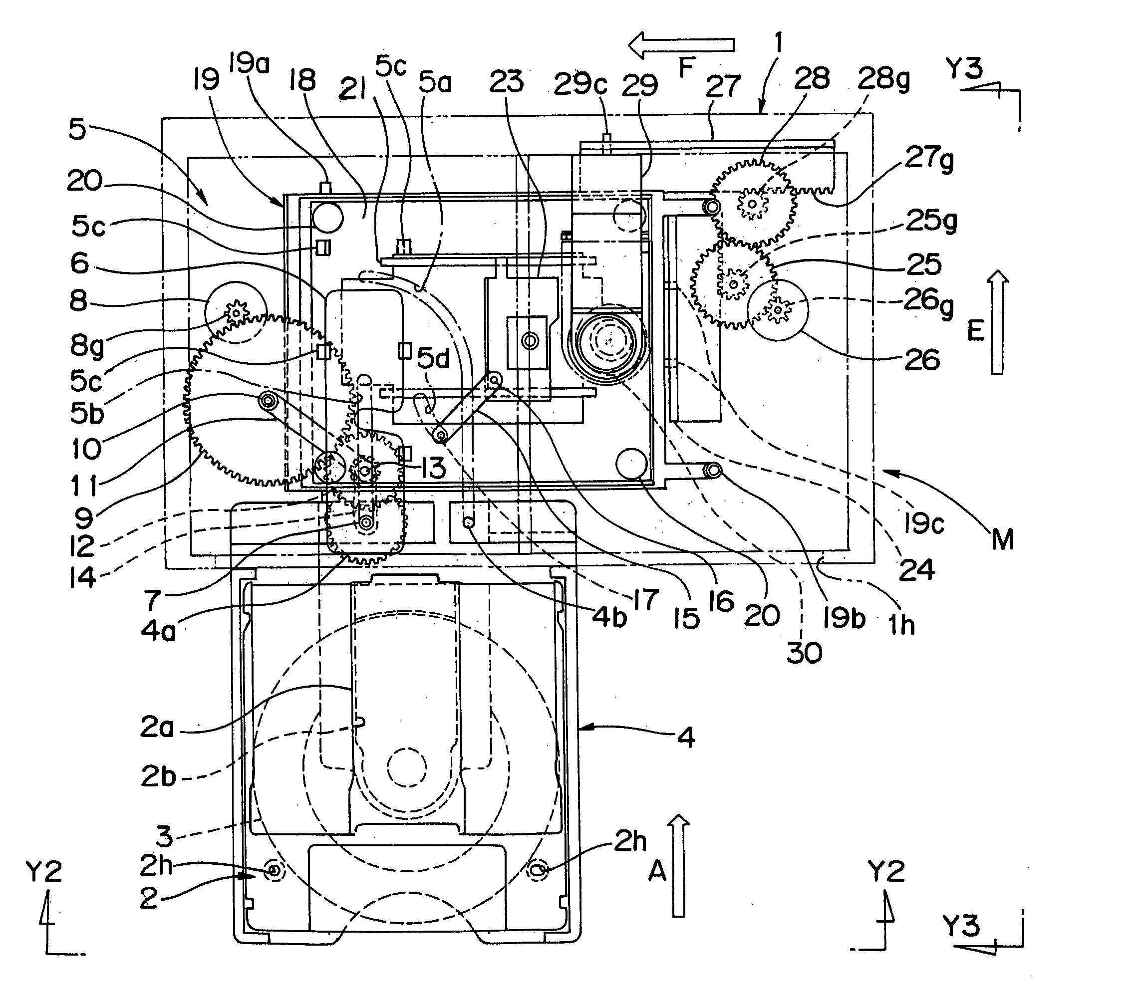
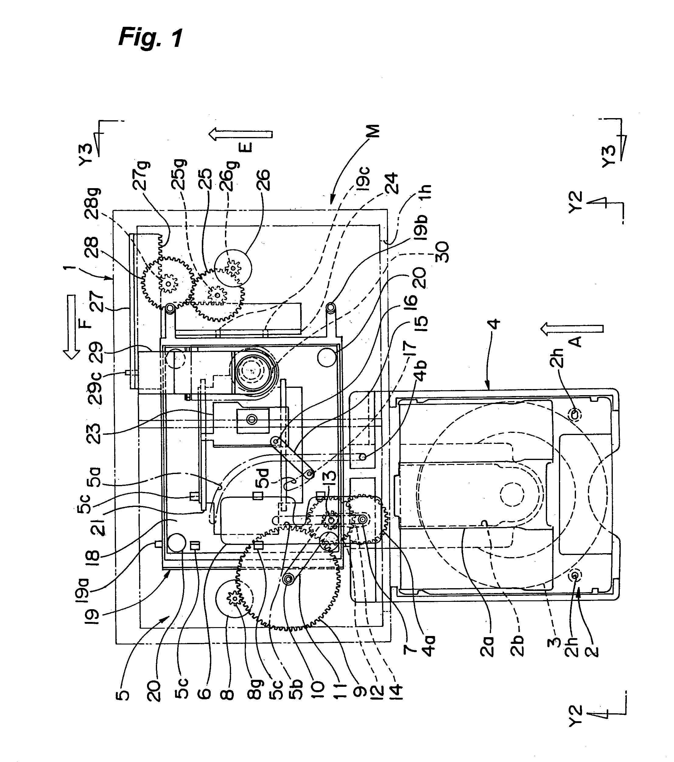
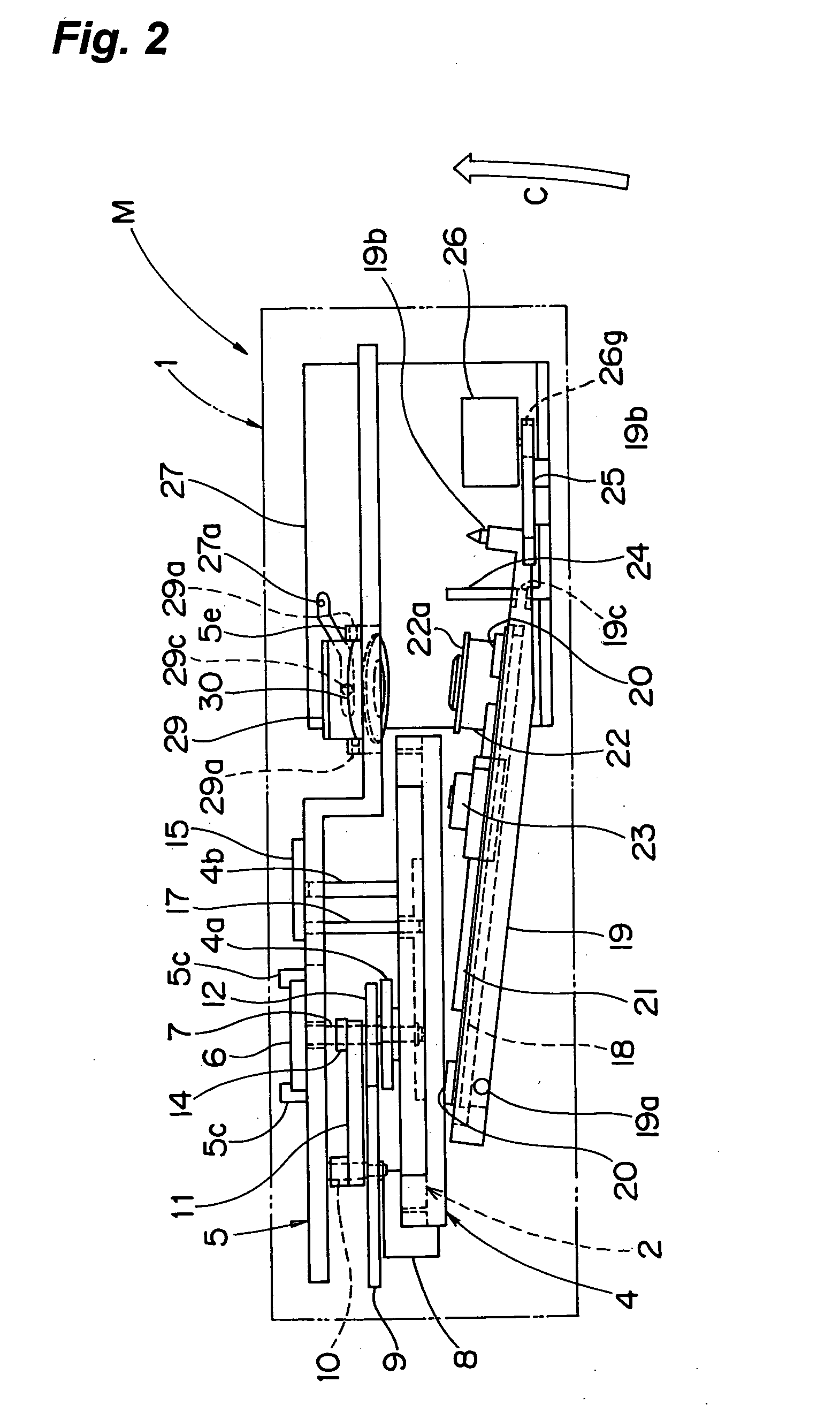
[0042]FIG. 1 is a plan explanatory drawing of a disk apparatus showing a state of drawing out a tray in a preferred embodiment of the invention. FIG. 2 is a front explanatory drawing of the disk apparatus, in an arrow view of Y2-Y2 in FIG. 1. FIG. 3 is a side explanatory drawing of the disk apparatus, in an arrow view of Y3-Y3 in FIG. 1. FIG. 4 is a plan explanatory drawing of magnified view of essential parts of disk conveying mechanism of the disk apparatus.

[0043] As shown in the drawings, a disk apparatus M in the preferred embodiment includes a box-shaped (rectangular parallelepiped) main body case 1 (chassis), and a disk tray 4 (hereinafter, occasionally referred to “tray” simply) provided in the main body case 1 to be movable in and out. The tray 4 is moved in and out of the main body case 1 by way of a disk access opening 1h provided at the front side of ...


PUM

PropertyMeasurementUnit
distanceaaaaaaaaaa
depth sizeaaaaaaaaaa
stabilityaaaaaaaaaa

Abstract

A disk conveying device provided in a disk apparatus, for conveying a disk between a first position outside of the disk apparatus and a second position inside of the disk apparatus, includes a swivel mechanism for swiveling the disk by 90 degrees substantially within a plane substantially parallel to the recording surface of the disk, at least in part of the conveying route between the first position and second position, thereby the disk conveying device is capable of shortening straight stroke of loading and unloading of disk and reducing the depth size of disk apparatus to realize a compact design.

Description

BACKGROUND OF THE INVENTION [0001] 1. Field of the Invention [0002] The present invention relates to a disk conveying device for conveying a disk as information recording medium between a first position outside of a disk apparatus and a second position inside of a disk apparatus, and a disk apparatus having such disk conveying device. [0003] 2. Description of the Related Art [0004] Conventionally, as a disk apparatus for recording and / or reproducing information signal in a disk as information recording medium, it is generally known to convey the disk between a disk loading and unloading position (first position) outside of the disk apparatus, and a recording and reproducing position (second position) inside of the disk apparatus. [0005] It is to be noted that, in the specification, “recording and / or reproducing” refers to “at least one of recording and reproducing” as an abbreviated form of expression. Also, the term “disk” refers to both “disk alone or bare disk” and “disk containe...

Claims


Application Information

Patent Timeline
Patent Type & Authority Applications(United States)
IPC IPC(8): G11B17/028G11B17/04
CPCG11B17/056G11B17/0288
Inventor MARUYAMA, MASUO
Owner PANASONIC CORP
Why Eureka
Try Eureka