System for dispensing reactant mixtures

a technology for reactant mixtures and systems, which is applied in the direction of packaging, liquid transfer devices, transportation and packaging, etc., can solve the problems of improper chemical reaction, difficult to predict the volume of reactant components that will be dispensed into the mixing chamber at any given time, and chemical reaction may occur too fas

Inactive Publication Date: 2005-05-12
FORD MOTOR CO
View PDF15 Cites 8 Cited by
  • Summary
  • Abstract
  • Description
  • Claims
  • Application Information

AI Technical Summary

Problems solved by technology

In addition, changes in temperature can affect the rate of expansion of the conduits, making it difficult to predict the volume of a reactant component that will be dispensed into the mixing chamber at any given ...

Method used


Image

  • System for dispensing reactant mixtures
  • System for dispensing reactant mixtures
  • System for dispensing reactant mixtures

Examples


Embodiment Construction

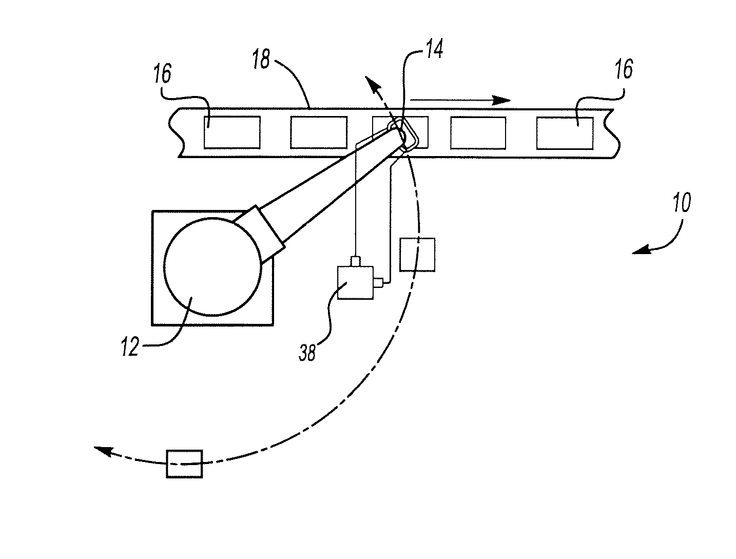
[0015] Referring now to FIG. 1, a multi-reactant injection system 10 is illustrated that may be used to inject a silicone sealant mixture on a production line. The system 10 uses a robot 12 to which a mixing chamber 14 is attached. A multiple component reactant mixture is injected through the mixing chamber 14 into a part 16 as it is moved by a conveyor 18.

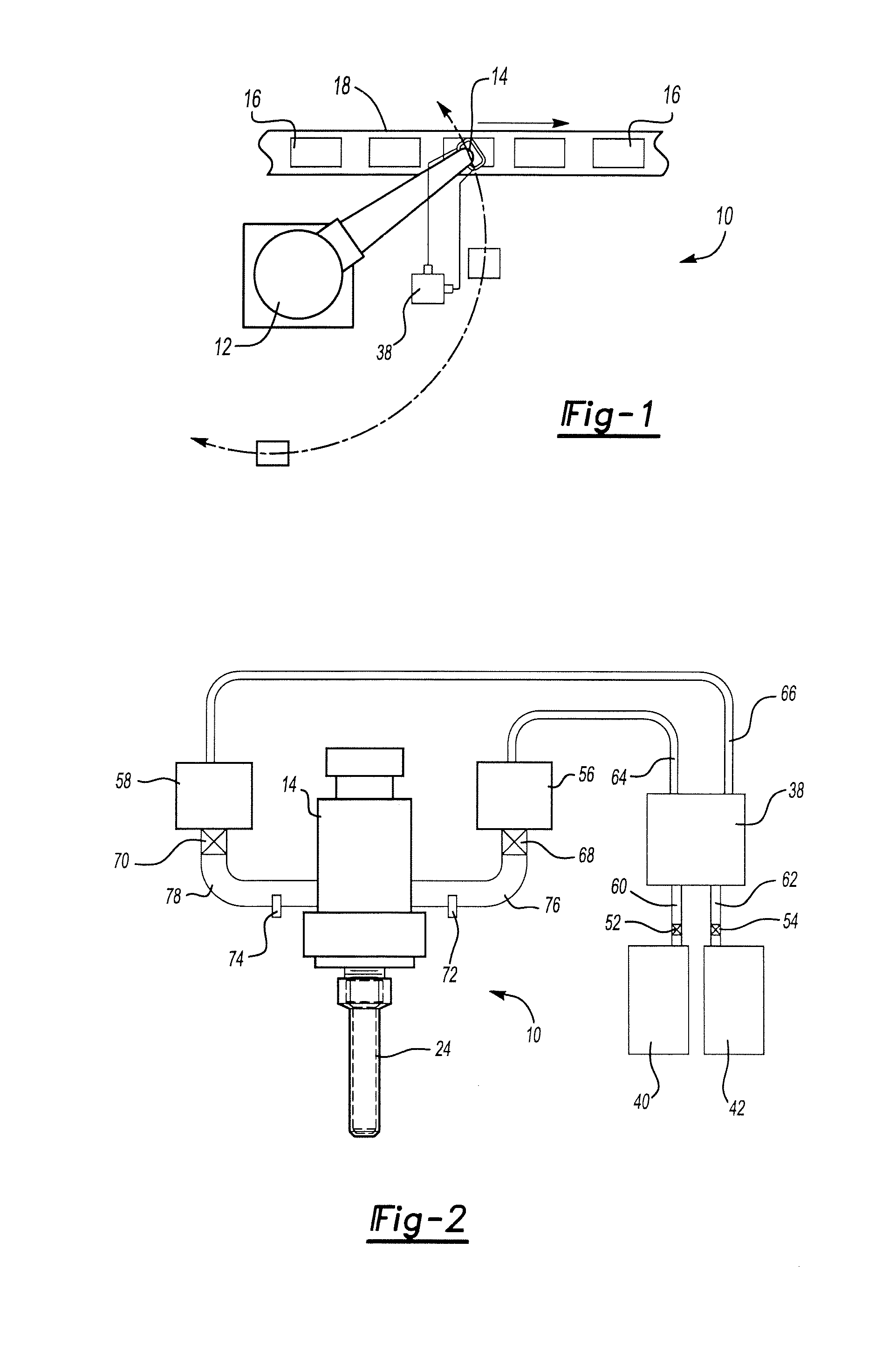
[0016] Referring now to FIG. 2, the multi-reactant injection system 10 is shown in greater detail. A catalyst supply 40 provides a catalyst to a metering ram 38 through a catalyst supply conduit 60. A catalyst shutoff valve 52 may be located in the catalyst supply conduit 60 between the catalyst supply 40 and the metering ram 38. The catalyst shutoff valve 52 can be used to control the flow of catalyst to the metering ram 38 and to prevent catalyst from flowing back into the catalyst supply 40. Similarly, a base supply 42 provides a base to the metering ram 38 through a base supply conduit 62. A base shutoff valve 54 may be locat...


PUM

PropertyMeasurementUnit
Pressureaaaaaaaaaa
Flow rateaaaaaaaaaa
Volumeaaaaaaaaaa

Abstract

A system for controlling dispensation of multiple component reactant mixtures. A mixing chamber is positioned adjacent to a part. A metering ram is actuated to pressurize at least two reactant components. The metering ram is stopped if a measured pressure value exceeds a predetermined pressure value. At least one flow meter measures a volume of a reactant component passing through the system.

Description

CROSS REFERENCE TO RELATED APPLICATIONS [0001] This application claims the benefit of U.S. provisional application Ser. No. 60 / 410,756, filed Sep. 13, 2002.BACKGROUND OF INVENTION [0002] 1. Field of the Invention [0003] The present invention relates to a system for controlling dispensation of multiple component reactant mixtures. [0004] 2. Background Art [0005] Multiple component reactant mixtures are used to form polymeric compositions. Examples of polymers formed by reactant mixtures include epoxies, polyurethanes, and silicone compositions. For example, a silicone seal may be formed by combining a two-part reactant mixture including a catalyst component and a base component that may be mixed and injected to form the silicone seal in situ in an assembly. [0006] Reactant mixtures are normally mixed in a mixing chamber of a gun injector that dispenses the mixture through a nozzle. The reactant components are provided under pressure to the mixing chamber via separate conduits. These ...

Claims


Application Information

Patent Timeline
IPC IPC(8): B05B7/04B05B7/12B05B7/24B05B13/04B29B7/76
CPCB05B7/0408B05B7/12B29B7/7631B05B13/0421B05B7/2489
Inventor SZYMANSKI, RICHARD JOHN
Owner FORD MOTOR CO
Why Eureka
Try Eureka