Combination writing instrument

a writing instrument and combination technology, applied in the field of writing instruments, can solve the problems of complex construction of such a writing instrument, difficult mass assembly, and inconvenient configuration

Active Publication Date: 2005-05-12
SOC DITE SOC BIC
View PDF13 Cites 27 Cited by
  • Summary
  • Abstract
  • Description
  • Claims
  • Application Information

AI Technical Summary

Benefits of technology

[0010] In accordance with another aspect of the present invention, a writing instrument is provided with a replaceable filler-type writing element having a a filler-type writing medium reservoir and a porous nib. A fluid-impervious sleeve preferably covers at least a portion of the porous nib and / or the filler-type writing medium reservoir of the writing element. The sleeve enables the user to handle the filler-type writing medium reservoir and the porous nib without getting writing medium on his / her hands and / or fingers. To enable refill of the writing element, the outer barrel of the writing instrument is designed to permit access to the writing element.

Problems solved by technology

The disadvantage of side-by-side construction is that the diameter of the pen barrel housing the writing elements must be greater than the diameter of a standard pen having only one writing element.
The construction of such a writing instrument thus is complex and difficult to assemble en mass.
Such a configuration is undesirable if an operator wants to use different types of writing mediums.
In addition, prior art writing instruments with multiple writing elements have not succeeded in providing disparate writing elements in a compact body having an outer diameter that is not significantly larger than the outer diameter of a standard, single writing element writing instrument.
Use of such writing instruments results in wasted motion when manipulating the orientation of the writing instrument to switch between writing ends to achieve different writing or marking modalities.
Thus, the use of both writing elements during a single writing / marking task requires the further wasted motions of removing and replacing two caps, instead of a single or no cap.

Method used


Image

  • Combination writing instrument
  • Combination writing instrument
  • Combination writing instrument

Examples


Embodiment Construction

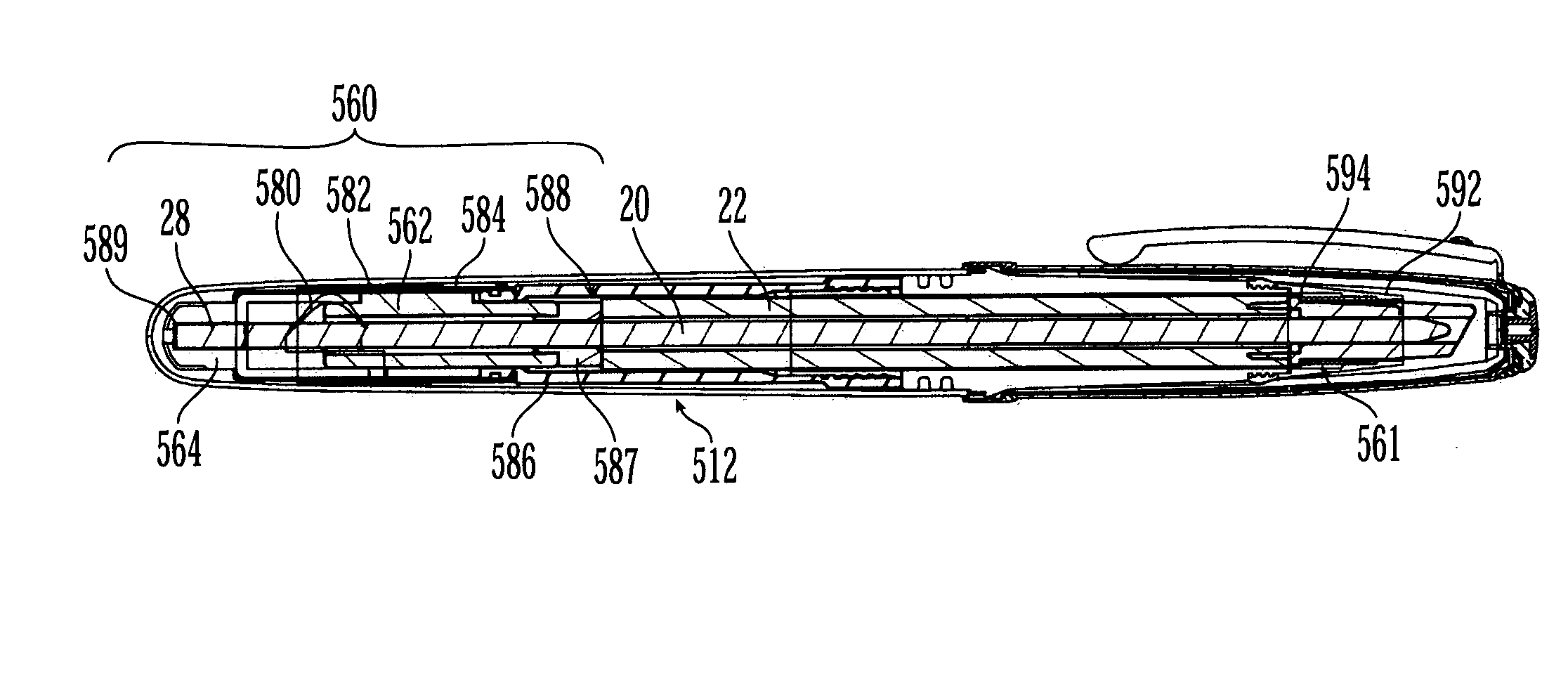
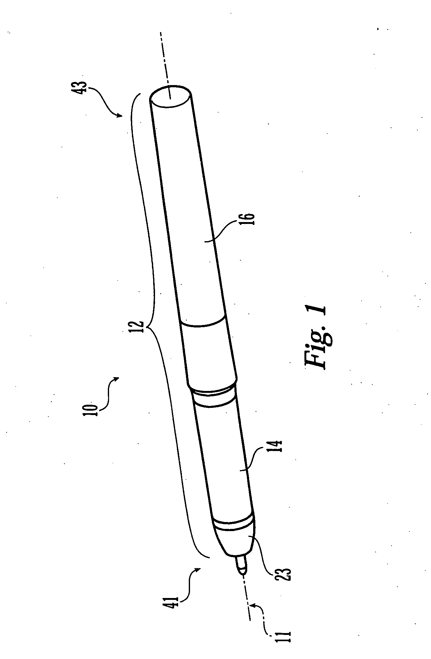
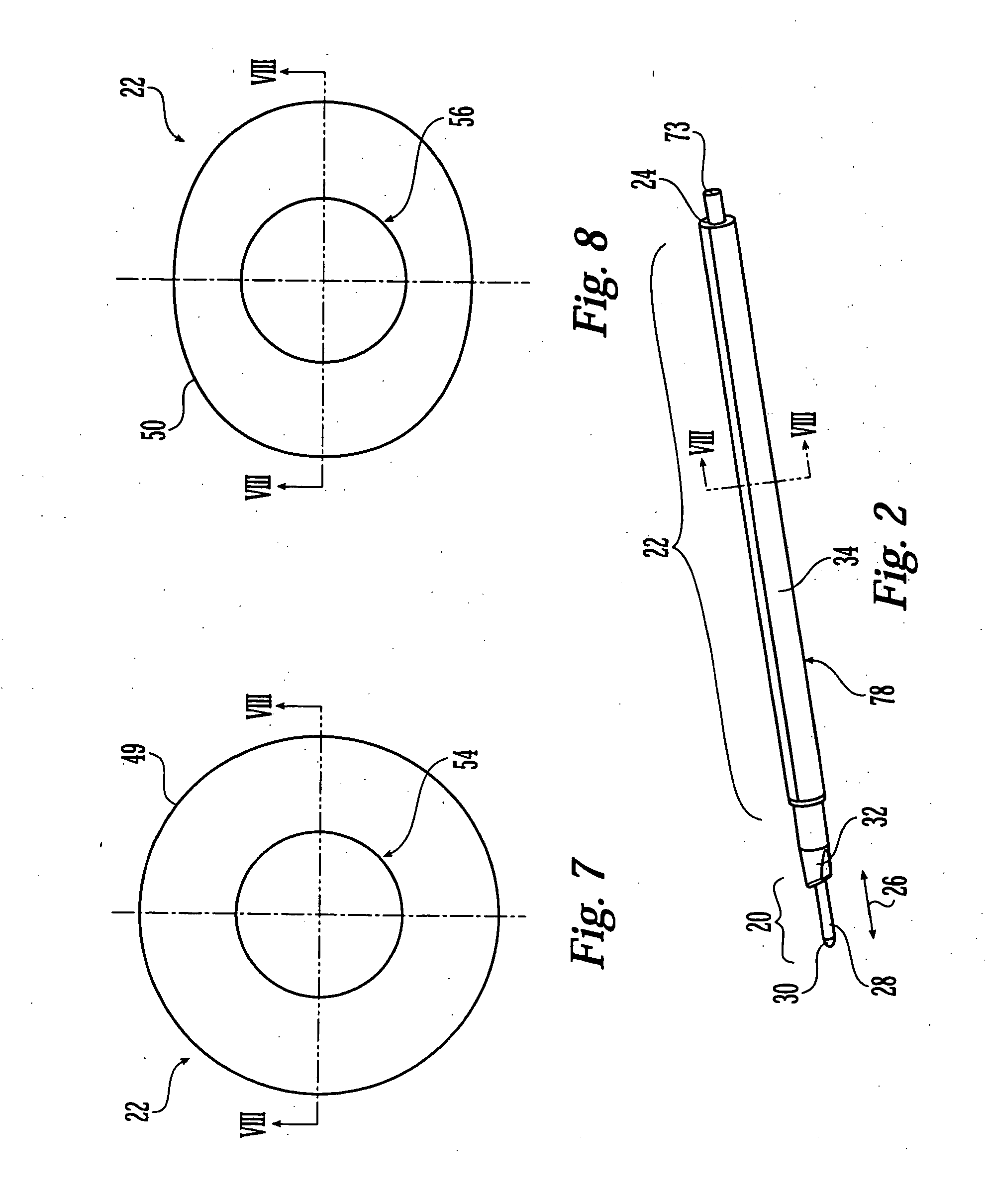
[0030] Referring now to FIG. 1, exemplary writing instrument 10 formed in accordance with the principles of the present invention, has an outer barrel 12 housing inner writing element 20 and outer writing element 22, such as illustrated in FIG. 2. It should be noted that the term “writing element” is not limited to a writing element in its literal sense but, instead, covers any element having any medium that can be applied to a substrate, including glue or correction fluid. Likewise, reference to “writing” or “marking,” or other such terms, is made for the sake of convenience. The terms “writing” or “marking” are not limited to writing and marking in their literal sense but, instead should be understood to include application of other mediums or substrates such as glue or correction fluid. As illustrated in the embodiment of FIGS. 1 and 3, outer barrel 12 may comprise front barrel 14, back barrel 16, and front nose cone 23, extending, preferably, along longitudinal axis 11. Front an...


PUM


Abstract

A writing instrument, which has an inner and outer writing element with separate writing medium reservoirs. The writing elements are coaxially mounted in an outer barrel and axially moveable with respect to one another. A driving mechanism may be actuated to allow a user to selectively extend one writing element. The inner and outer writing elements may have an inner sleeve therebetween to improve, for instance, rigidity of the outer writing element and to prevent contamination of the writing medium reservoirs. An outer sleeve may also be provided over the outer writing element. The outer sleeve can function to hold various components of the outer writing element together, and to allow for clean and easy refill of the outer writing element, especially when the outer writing element is a porous nib with a filler-type writing medium reservoir. The writing instrument is designed so that a user can replace the inner and/or outer writing elements when their respective writing medium have been expended.

Description

CROSS-REFERENCE TO RELATED APPLICATION [0001] The present application is a continuation-in-part of U.S. patent application Ser. No. 10 / 706,315 filed Nov. 11, 2003, which application is hereby incorporated by reference in its entirety.FIELD OF THE INVENTION [0002] The present invention relates to a writing instrument and, in particular, a writing instrument having at least two writing elements that are axially moveable with respect to one another, and more particularly, with one writing element being disposed within the other writing element. The present invention also relates to improvements to filler-type writing instruments. BACKGROUND OF THE INVENTION [0003] Writing instruments having multiple writing elements are well known in the art. For the most part, these writing instruments have a plurality of writing elements disposed adjacent (side-by-side) to one another within a pen barrel. Prior art writing instruments have combined a variety of types of writing elements, including ba...

Claims


Application Information

Patent Timeline
Patent Type & Authority Applications(United States)
IPC IPC(8): B43KB43K5/00B43K27/00
CPCB43K1/006B43M11/06B43K5/14B43K7/005B43K8/003B43K8/02B43K8/03B43K21/006B43K23/08B43K23/126B43K24/14B43K24/16B43K25/022B43K27/02B43K27/08B43K29/05B43L19/0018B43L19/0081B43K5/005
Inventor BEDHOME, VINCENTCOOPER, KENNETH R.EDGERLEY, DAVID ANTHONYHUNGERFORD, DOUGLASLANGE, DIDIERMATTHEWS, ROBERT EDWARDROLLION, FRANCKWLODARCZYK, ANTHONYEDDINGTON, RYAN
Owner SOC DITE SOC BIC
Why Eureka
Try Eureka