IP multicast communication system

a multicast communication and communication system technology, applied in multiplex communication, data switching networks, data switching details, etc., can solve problems such as delay in data encryption and decryption, acquisition of multicast data, and difficulty in controlling multicast data access from recipients, so as to prevent or disturb the reception of multicast data

Inactive Publication Date: 2005-05-26
FUJITSU LTD
View PDF22 Cites 62 Cited by
  • Summary
  • Abstract
  • Description
  • Claims
  • Application Information

AI Technical Summary

Benefits of technology

The technical effect of this patent is that it describes how to use information from an internet protocol called IGMP to stop people from receiving unwanted email-like messages (called multicast data) without permission.

Problems solved by technology

This patent describes an improved way to send music and videos over the internet to multiple people simultaneously without allowing others to easily get the content without permission. The problem has been solved by creating a new system that uses advanced technology to verify who should receive the content and what type of security measures are needed to protect against unauthorized access.

Method used


Image

  • IP multicast communication system
  • IP multicast communication system
  • IP multicast communication system

Examples


Embodiment Construction

[0036] Next, an embodiment of the present invention is described referring to the drawings.

[0037] [Configurations of IP Multicast Communication System]

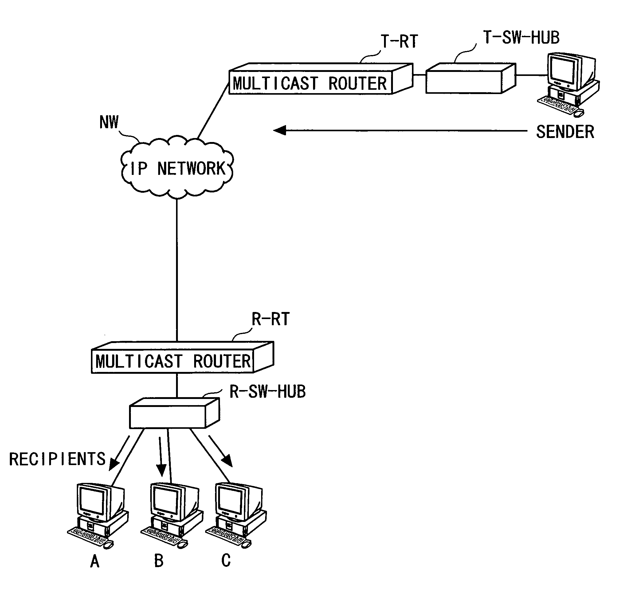
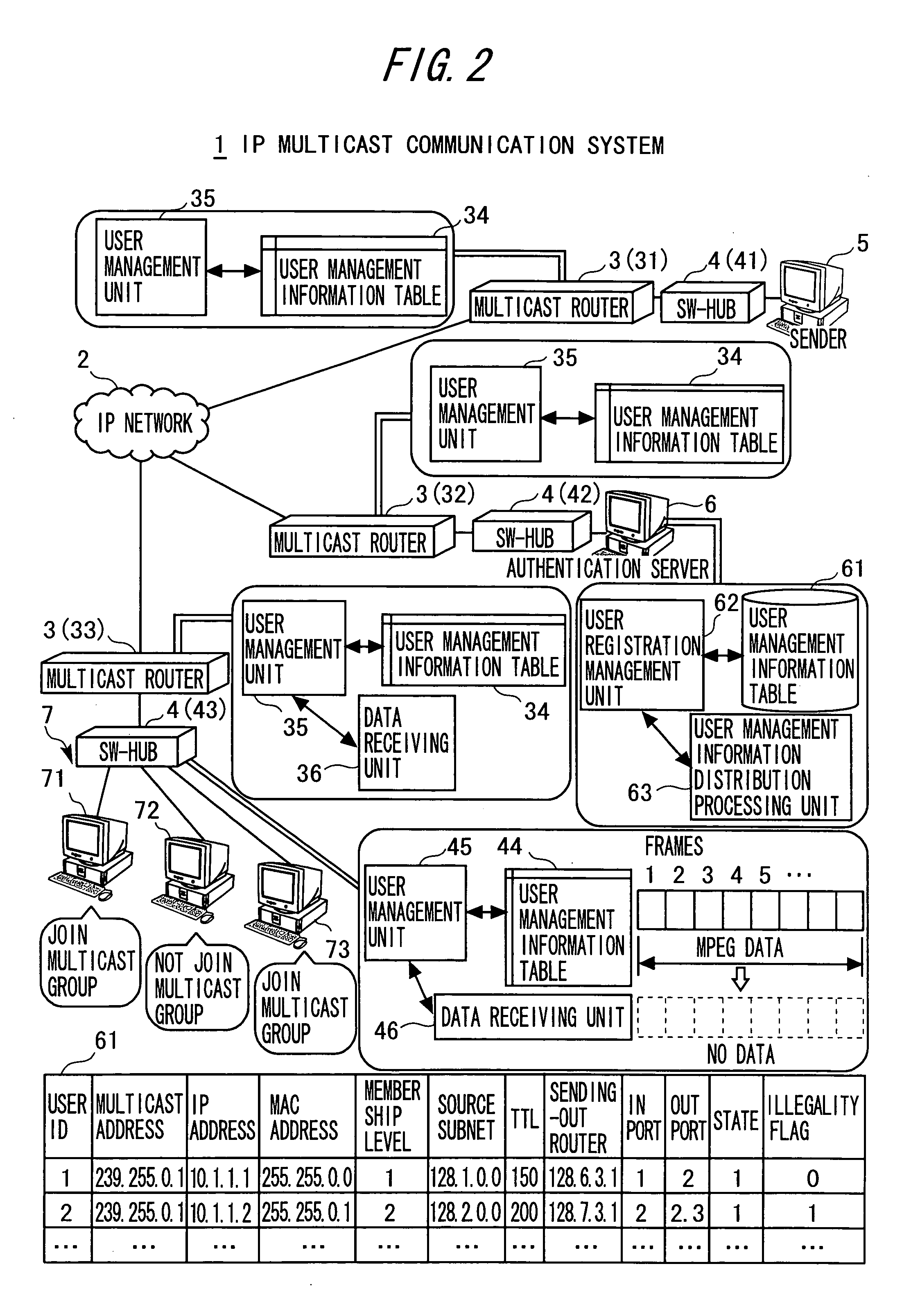
[0038] Referring to FIGS. 2 and 3 showing system configurations according to an embodiment of the present invention, an IP multicast communication system 1 includes multicast routers 3 (31, 32, and 33) connected to an IP network 2, e.g. the Internet.

[0039] These multicast routers 3 are provided for respective subnetworks (subnets) and connected to respective subordinate switching hubs (SW-HUBs) 4 (41, 42, and 43). The multicast routers 3 can be replaced by other layer-3 (L3) switches that support IP multicasting.

[0040] The switching hub 41 accommodates a sender 5 that sends IP multicast data (strictly, including a sending terminal such as a host / server computer and its operator). The switching hub 42 accommodates an authentication server 6. The switching hubs 41 and 42 may be omitted. Also, the switching hubs 41 and 42 may be repla...


PUM


Abstract

An IP multicast communication system includes a layer-2 switch for accommodating a plurality of recipients dynamically joining or not joining a multicast group, a layer-3 switch adapted to a subnet for receiving IP multicast data sent from a sender via an IP network and distributing the received IP multicast data to authorized recipients joining the multicast group via the layer-2 switch under control, and a controller for collectively managing recipient management information for authentication of the recipients obtained according to an Internet Group Management Protocol IGMP. The layer-3 switch authenticates the recipients according to the recipient management information adapted to its subnetwork among the recipient management information collectively managed by the controller. The layer-2 switch stops transmission of the IP multicast data or thins the IP multicast data sent to recipients that are determined to have made unauthorized accesses by the layer-3 switch.

Description


Claims


Application Information

Patent Timeline
Owner FUJITSU LTD
Why Eureka
Try Eureka