Method and system for system visualization

a system visualization and system technology, applied in the field of information display, can solve the problems of user loss in the rendered image, few, if any, of the real world visual clues normally available, and difficulty and/or problems

Active Publication Date: 2005-06-16
PRESIDIO LABS
View PDF26 Cites 34 Cited by
  • Summary
  • Abstract
  • Description
  • Claims
  • Application Information

AI Technical Summary

Benefits of technology

[0010] The above and other preferred features, including various novel details of implementation and combination of elements, will now be more particularly described with reference to the accompanying drawings and pointed out in the claims. It will be understood that the particular meth...

Problems solved by technology

While the sheer amount of information which can be represented within an information visualization system and the ease with which the representations employed within the landscape allow assimilation of the information by a user are some of the advantages offered by such systems, they can also lead to some difficulties and/or problems.
For example, while most users of visualiz...

Method used


Image

  • Method and system for system visualization
  • Method and system for system visualization
  • Method and system for system visualization

Examples


Embodiment Construction

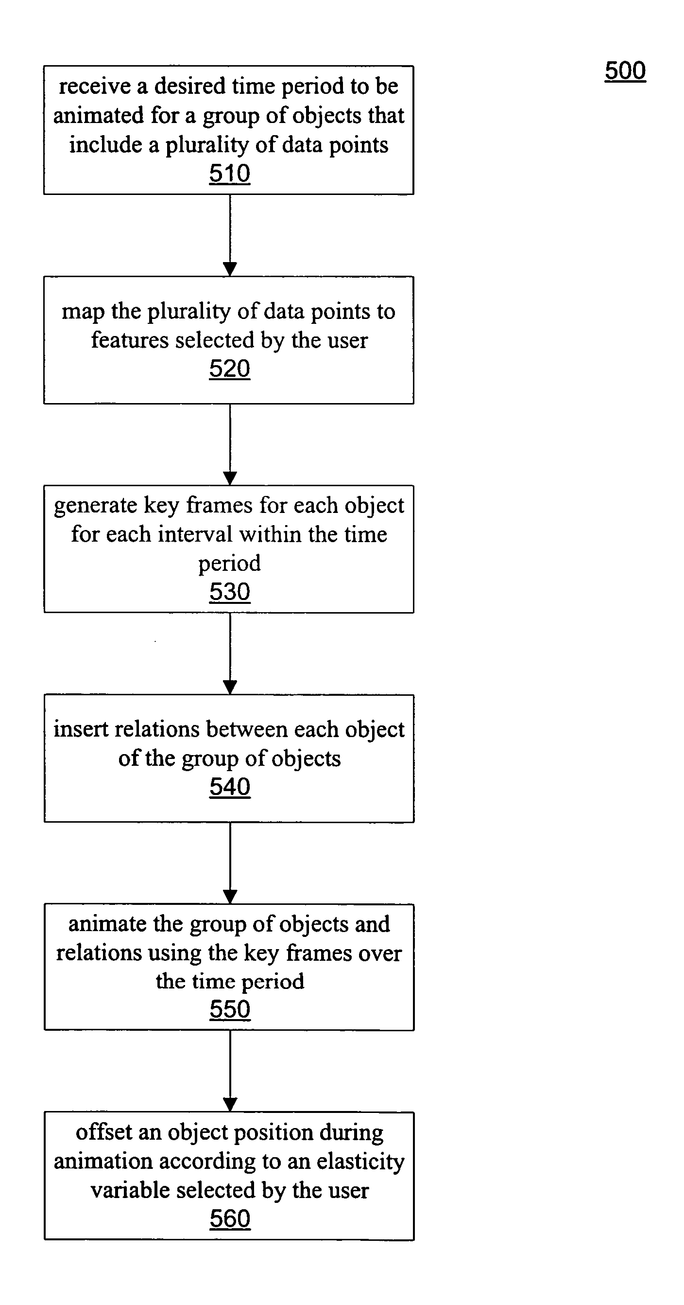
[0017] A method and system for system visualization is disclosed. In one embodiment, a computer-implemented method comprises receiving a time period indication selected by a user for a group of objects including a plurality of data points. The plurality of data points are mapped to features selected by the user. Key frames are generated for the group of objects for each interval of time of the time period. Relations can be inserted between any pair of objects. The group of objects and relations are rendered using the key frames over the time period to generate an animation. An object position is offset during animation according to an elasticity variable associated with the relations that is selected by the user. Positions in between key frames are interpolated to provide smooth rendering between variable time frames. In an alternate embodiment, the object position is offset during animation according to features of the group of objects (mapped object properties) selected by the use...


PUM


Abstract

In one embodiment, a computer-implemented method comprises receiving a time period indication selected by a user for a group of objects including a plurality of data points. The plurality of data points are mapped to features selected by the user. Key frames are generated for the group of objects for each interval of time of the time period. Relations can be inserted between any pair of objects. The group of objects and relations are rendered using the key frames over the time period to generate an animation. An object position is offset during animation according to an elasticity variable associated with the relations that is selected by the user. Positions in between key frames are interpolated to provide smooth rendering between variable time frames. In an alternate embodiment, the object position is offset during animation according to features of the group of objects selected by the user, with or without the elasticity variable.

Description

[0001] The present application claims the benefit of and priority to U.S. Provisional Patent Application No. 60 / 529,052 entitled “Universal n-dimensional onto-holotropic space time information utilization,” and filed on Dec. 12, 2003, and is hereby, incorporated by reference.FIELD OF THE INVENTION [0002] The field of the invention relates generally to information display, and more particularly relates to a method and system for system visualization. BACKGROUND OF THE INVENTION [0003] Systems are being developed for representing information as rendered static three-dimensional (3D) images. One example of such systems relate to financial information. Financial and economic information relating to stock or bond prices and trading activities are presented in a 3D data landscape. Within this data landscape, various rendered 2D or 3D objects (such as blocks, surfaces, etc.) can represent different stocks, bonds or other items of interest and the condition (size, color, position, etc.) of ...

Claims


Application Information

Patent Timeline
IPC IPC(8): G06FG06T13/20G06T15/20
CPCG06T19/00G06T13/20
Inventor WARNER, MICHAEL S.PANTERA, PAUL
Owner PRESIDIO LABS
Why Eureka
Try Eureka