Ring stent

a ring stent and stent technology, applied in the field of stents, can solve the problems of not having good dimensional stability, difficult sealing of stent grafts, and stents may be covered or uncovered, so as to achieve good sealing, give dimensional stability, and dimensionally stable surfaces

Active Publication Date: 2005-06-16
COOK MEDICAL TECH LLC
View PDF15 Cites 71 Cited by
  • Summary
  • Abstract
  • Description
  • Claims
  • Application Information

AI Technical Summary

Benefits of technology

This patent describes a type of stent that can be used to keep blood vessels open after they have been repaired with a stent graft. These stents are designed to prevent any leaks or blockages when there are certain parts of the stent graft that meet up against the walls of the blood vessel. They can also help create a smooth transition between different sections of the stent graft by providing a secure and reliable connection point.

Problems solved by technology

The technical problem addressed in this patent relates to improving the design of stents to ensure better fixation and reduction of inflammation while maintaining optimal blood flow through bodily vessels.

Method used


Image

  • Ring stent
  • Ring stent
  • Ring stent

Examples


Embodiment Construction

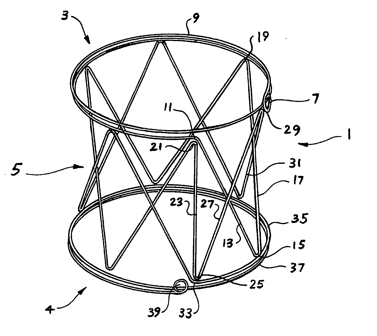
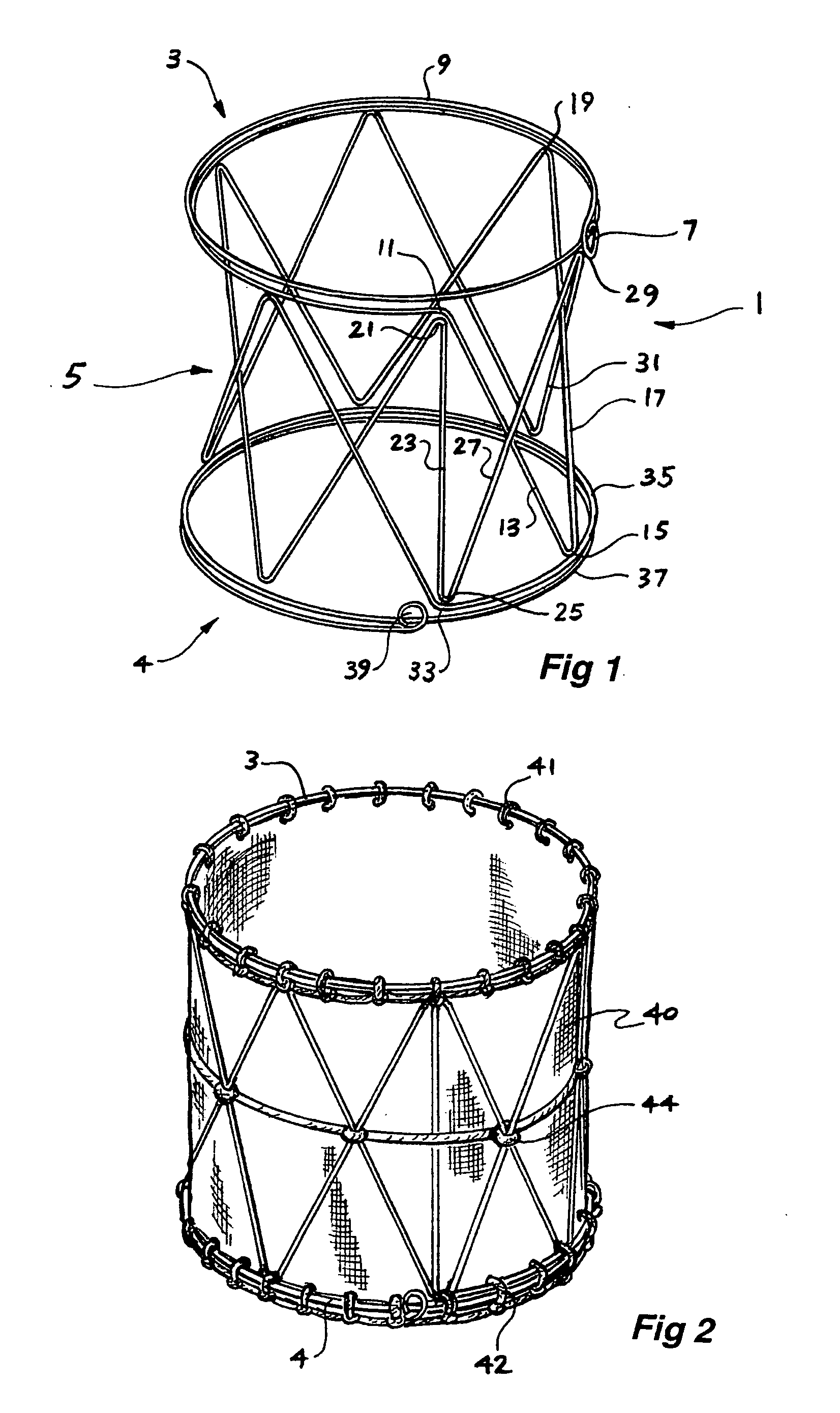
[0074] Now looking more closely at the drawings and in particular FIG. 1, it will be seen that the stent 1 according to one embodiment of this invention comprises a first resilient ring assembly 3 and a second resilient ring assembly 4 spaced (preferably parallel) to and axially away from the first ring assembly 3 and a number of zig zag struts 5 between the first resilient ring assembly 3 and the second resilient ring assembly 4. The first and second resilient ring assemblies and the struts comprise a metallic wire.

[0075] Although metal or metal alloy materials are preferred other resilient materials such as polymers, carbon fibres and other biocompatible materials are also contemplated.

[0076] The first ring assembly 3 commences at a loop 7 of the wire and is formed from two circles or turns of wire 9 and then at 11 there is a bend and the wire is angled in a first strut 13 extending to a bend 15 adjacent the second ring assembly 4 and then a further angled strut 17 to a bend 19 ...


PUM


Abstract

A stent arrangement which has at least a first ring ( 3 ) and zig zag struts ( 5 ) extending axially from the periphery of the ring. There can be first and second rings ( 3, 4 ) axially spaced apart and defining substantially parallel planes and a plurality of zig zag portions ( 5 ) between the first and second ring portions around the periphery thereof. The stent can be formed from a single wire or laser cut from a cannula and can be covered or uncovered.

Description


Claims


Application Information

Patent Timeline
Owner COOK MEDICAL TECH LLC
Why Eureka
Try Eureka