Adjusting Device for Camshafts, Particularly for Motor Vehicles

Inactive Publication Date: 2005-06-23
HYDRAULIK RING
View PDF6 Cites 13 Cited by
  • Summary
  • Abstract
  • Description
  • Claims
  • Application Information

AI Technical Summary

Benefits of technology

[0005] It is an object of the present invention to configure the adjusting device of the aforementioned kind such that, in a

Problems solved by technology

When starting the engine again, this can cause problems when the rotor

Method used


Image

  • Adjusting Device for Camshafts, Particularly for Motor Vehicles
  • Adjusting Device for Camshafts, Particularly for Motor Vehicles
  • Adjusting Device for Camshafts, Particularly for Motor Vehicles

Examples


Example

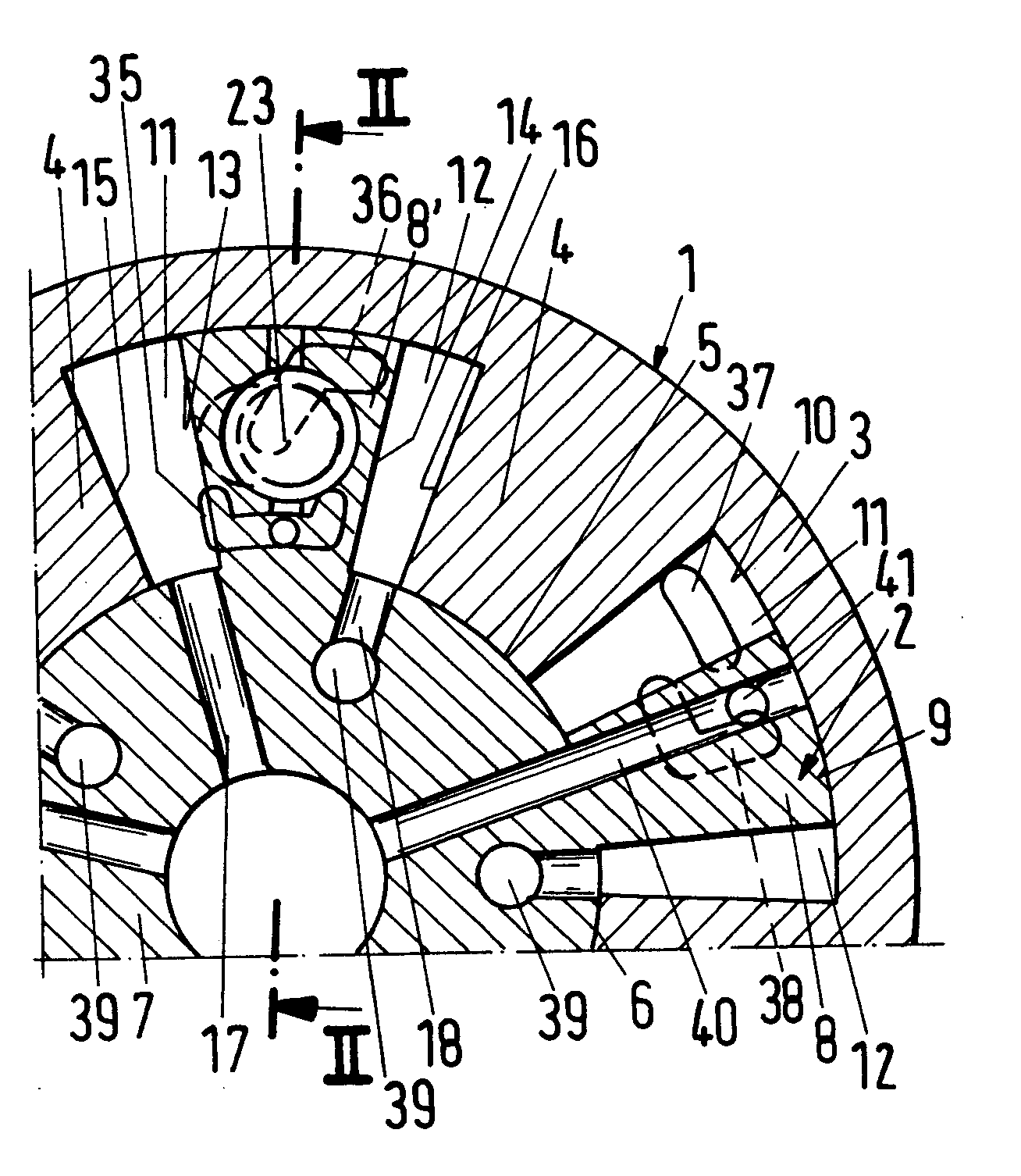
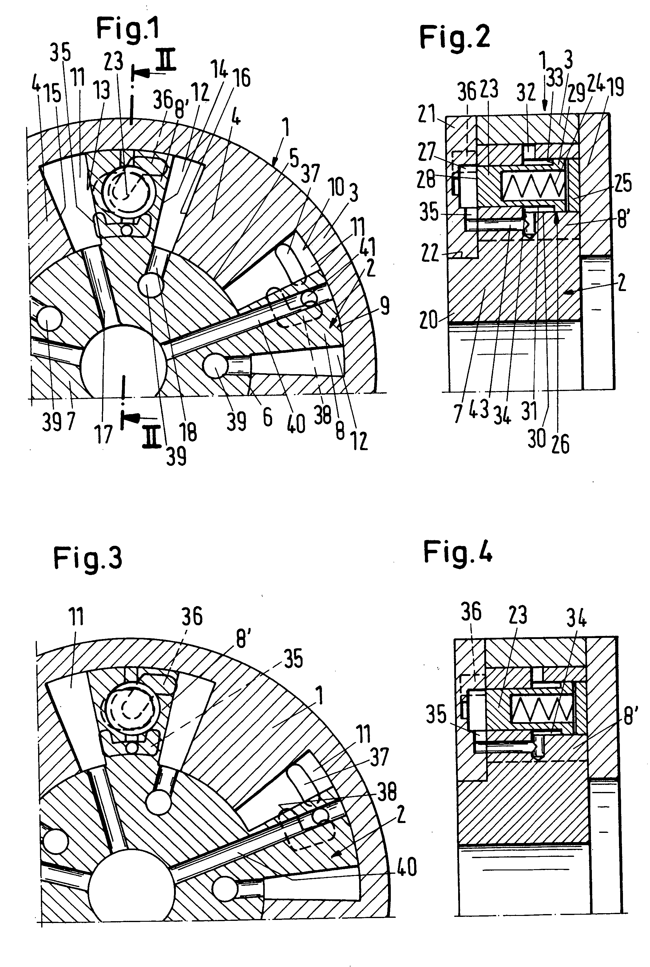
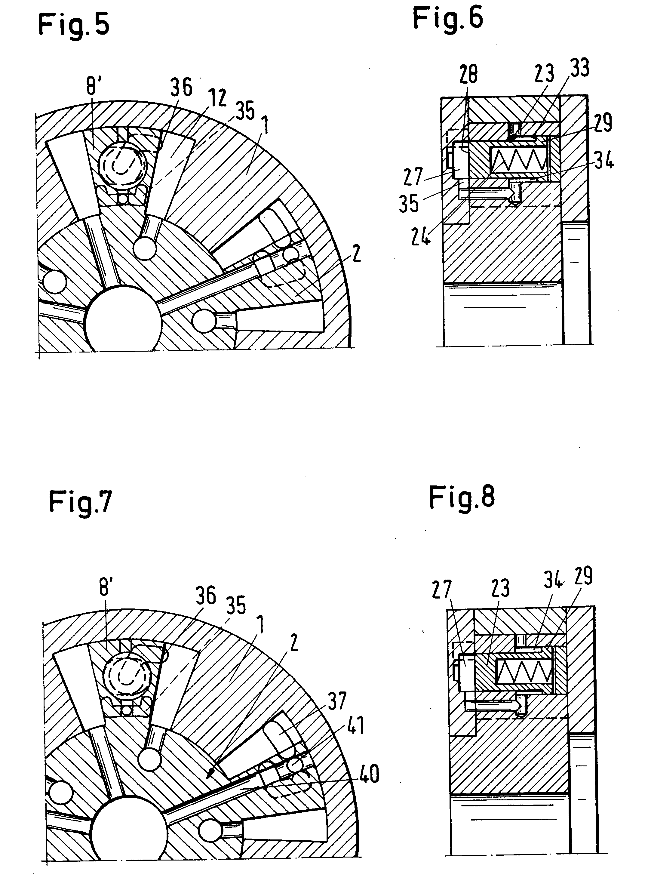
[0036] The adjusting device is part of a camshaft adjusting device that is used in connection with motor vehicles. The basic configuration of such adjusting devices is known and is therefore not explained in detail.

[0037] The adjusting device has a stator 1 in which a rotor 2 is arranged to be rotatably to a limited extent. The configurations of the stator and of the rotor are known in general and are therefore only discussed briefly. The stator 1 has a cylindrical casing 3 and stays 4 projecting radially inwardly away from the casing 3. The stays 4 have the same angular spacing relative to one another.

[0038] The end faces 5 of the stays 4 rest a really against the cylindrical peripheral surface 6 of a base member 7 of the rotor 2. Vanes 8 project radially from the peripheral surface 6 of the base member 7 and rest with their curved free end faces 9 areally against the cylindrical inner wall 10 of the casing 3 of the stator 1. The vanes 8 widen in the direction toward the casing 3...


PUM


Abstract

An adjusting device for camshafts of motor vehicles has a stator having radial inwardly projecting stays and a rotor having vanes projecting into spaces defined between the stays of the stator. The rotor is rotatable relative to the stator and the vanes of the rotor are loadable on opposed sides with a pressure medium. The rotor is lockable relative to the stator in a locked position, wherein the stator has at least one locking bore and the rotor has a locking element having a locking position in which the locking element engages the locking bore and locks the rotor in the locked position. The locking element is moveable by the pressure medium from the locking position into a release position.

Description

BACKGROUND OF INVENTION [0001] 1. Field of the Invention [0002] The invention relates to an adjusting device for camshafts, in particular, camshafts of motor vehicles, comprising a stator having radially inwardly projecting stays. A rotor is arranged rotatably relative the stator. The vanes of the rotor project into the space between the stays. The vanes of the rotor can be loaded on opposed sides by a pressure medium. [0003] 2. Description of the Related Art [0004] By means of the adjusting device, the camshaft is adjusted by rotation of the rotor relative to the stator. When the motor is turned off, the rotor remains in its current position relative to the stator. When starting the engine again, this can cause problems when the rotor has assumed an unfavorable rotational position relative to the stator. SUMMARY OF INVENTION [0005] It is an object of the present invention to configure the adjusting device of the aforementioned kind such that, in a constructively simple and reliable...

Claims


Application Information

Patent Timeline
IPC IPC(8): F01L1/34F01L1/344
CPCF01L1/3442F01L2001/34456F01L2001/34469F01L2001/34463F01L2001/34459
Inventor KNECHT, ANDREASSLUKA, GEROLDPALESCH, EDWIN
Owner HYDRAULIK RING
Why Eureka
Try Eureka