Flash lighting for image acquisition

a technology of flash lighting and image acquisition, applied in the direction of instrumentation, color signal processing circuit, exposure control, etc., can solve the problems of limited control of image characteristics and inconvenient use of filters

Active Publication Date: 2005-06-23
EPISTAR CORP
View PDF37 Cites 136 Cited by
  • Summary
  • Abstract
  • Description
  • Claims
  • Application Information

AI Technical Summary

Problems solved by technology

However, this provides only limited control of image characteristics because the filters do not provide continuous control of the spectral content of the light...

Method used


Image

  • Flash lighting for image acquisition
  • Flash lighting for image acquisition
  • Flash lighting for image acquisition

Examples


Embodiment Construction

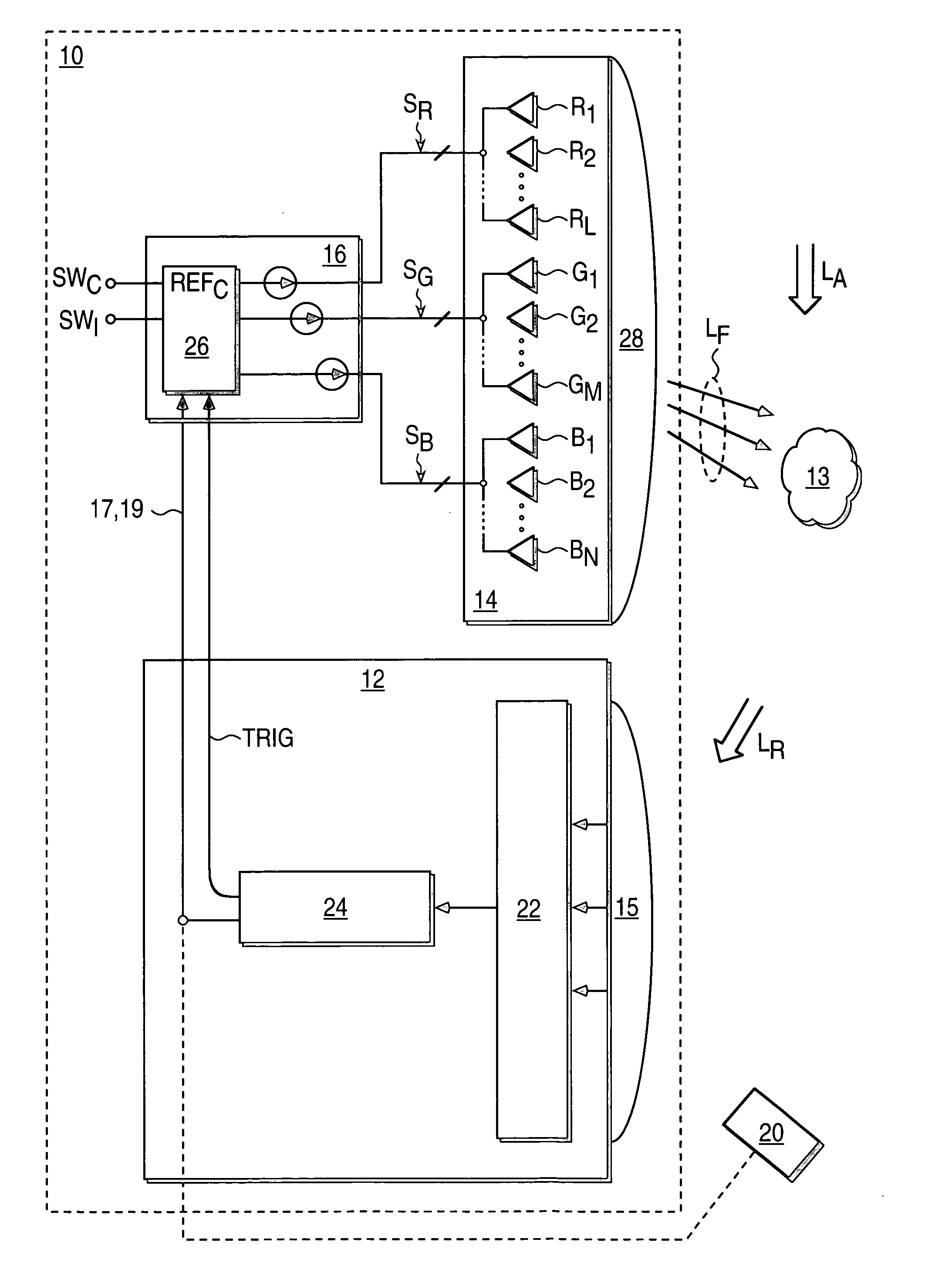
[0009]FIG. 1 shows a block diagram of an imaging system 10 according to embodiments of the present invention. The imaging system 10 includes a camera 12 and a light module 14 associated with the camera 12. The light module 14 has a series of emitters of light of at least two different colors, where the emitters are indicated as R1-RL, G1-GM, B1-BN. The subscripts L, M, N are integers that represent the number of red emitters, blue emitters and green emitters, respectively. In a typically application, the number of emitters of each color is equal.

[0010] In this example, the different colors are red, green and blue, although emitters of other colors are alternatively used to provide a sufficiently wide spectral content adjustment range. A driver 16 provides drive signals SR, SG, SB to these different color emitters R1-RL, G1-GM, B1-BN, respectively. By varying the drive signals corresponding to the different color emitters in the series, the spectral content of flash light LF provide...


PUM


Abstract

A light module associated with the camera provides flash light having a spectral content that is adjustable according to one or more drive signals. The light module includes one or more emitters of light of at least two different colors that are individually accessible to the one or more drive signals. The flash light is a mixture of the light from the one or more emitters.

Description

BACKGROUND OF THE INVENTION [0001] Strobed light sources or “flashes” provide supplemental light for photographic subjects while images of the subjects are acquired by a camera or other imaging system. One common type of flash includes a xenon bulb that emits light based on the discharge of xenon gas. The spectral content of this light is fixed by the characteristics of the gas discharge, which in turn fixes the color temperature of the supplemental lighting for the photographic subject. Another type of flash, included with the cameras integrated into mobile phones, comprises one or more “white” LEDs. The “white” LEDs are typically formed using one or more blue LEDs (primary emitters) with phosphors (secondary emitters) deposited on the blue LEDs. The spectral content of the light emitted by the “white” LEDs is also fixed, depending on the spectral characteristics of the primary emitters and the emission characteristics of the deposited secondary emitters, which fixes the color temp...

Claims


Application Information

Patent Timeline
IPC IPC(8): G03B7/16G03B15/02G03B15/03G03B15/05G03B17/02G03B19/02H04N5/222H04N5/225H04N5/235H04N5/238H04N9/04H04N9/73
CPCG03B15/02H04N9/735H04N5/2354H04N23/74H04N23/88H04N23/75
Inventor LEE, KIAN SHINYIN CHUA, JANET BEELAU, YUE HOONGSEAH, TEOH TEHLEE, JOON CHOK
Owner EPISTAR CORP
Why Eureka
Try Eureka