Stator vane assembly for a gas turbine engine

a gas turbine engine and stator vane technology, which is applied in the direction of machines/engines, liquid fuel engines, lighting and heating apparatus, etc., can solve the problems of limiting the utilization of full hoop outer shrouds in certain areas of gas turbine engines, unable to effectively withstand the high pressure and temperature environment of modern gas turbine engines, and the design of full hoop outer shrouds may be too stiff to permit conventional stress management through shroud flexibility, etc., to achiev

Active Publication Date: 2005-06-23
RAYTHEON TECH CORP
View PDF12 Cites 24 Cited by
  • Summary
  • Abstract
  • Description
  • Claims
  • Application Information

AI Technical Summary

Benefits of technology

[0009] The present invention therefore provides a stator assembly with a full hoop outer shroud that satisfies

Problems solved by technology

Although effective, conventional pierced shroud arrangements may not effectively withstand the high pressure and temperature environments in modern gas turbine engines over prolonged time periods.
However, a full hoop design may be too stiff to permit conve

Method used


Image

  • Stator vane assembly for a gas turbine engine
  • Stator vane assembly for a gas turbine engine
  • Stator vane assembly for a gas turbine engine

Examples


Embodiment Construction

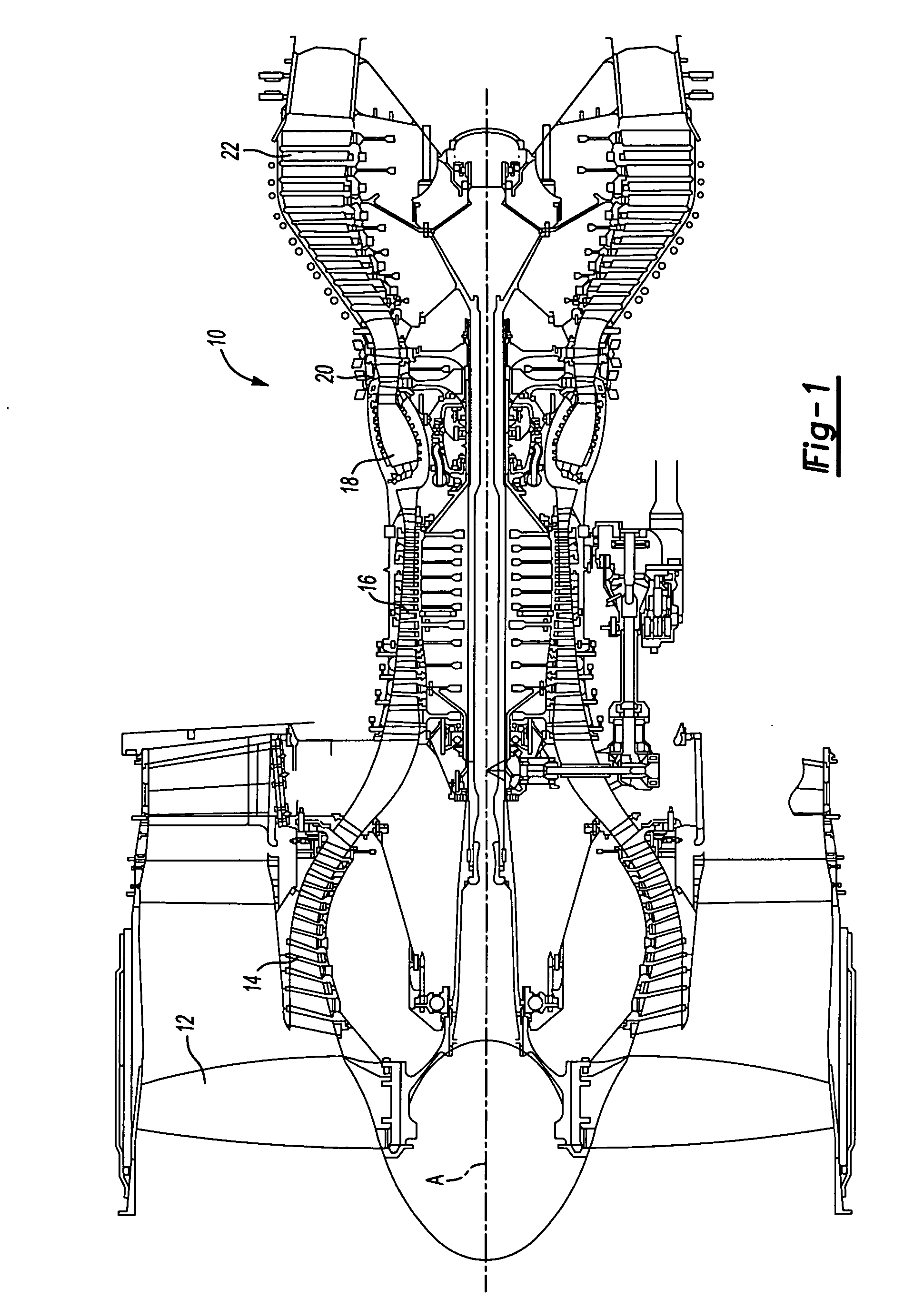
[0016]FIG. 1 illustrates a general schematic sectional view of a gas turbine engine 10. The gas turbine engine 10 is defined about an engine centerline A about which the various engine sections rotate. Generally, the engine 10 includes a fan section 12, a low pressure compressor section (LPC) 14, a high pressure compressor section (HPC) 16, a combustor section 18, a high pressure turbine section 20 and a low pressure turbine section 22. It should be understood that although a particular arrangement is disclosed in the illustrated embodiment, other arrangements will benefit from the instant invention including gas turbines used for electrical power generation and for aircraft.

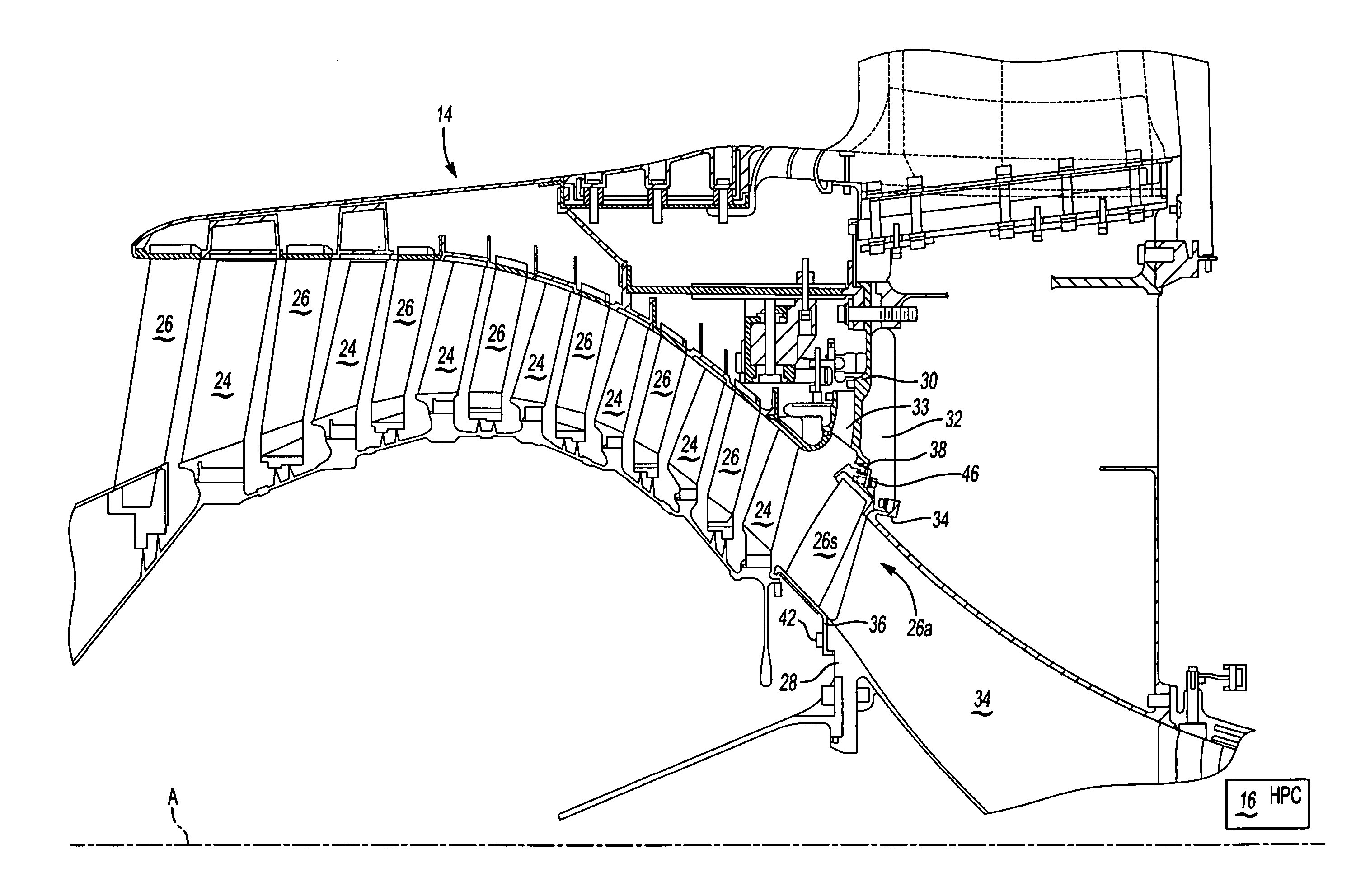
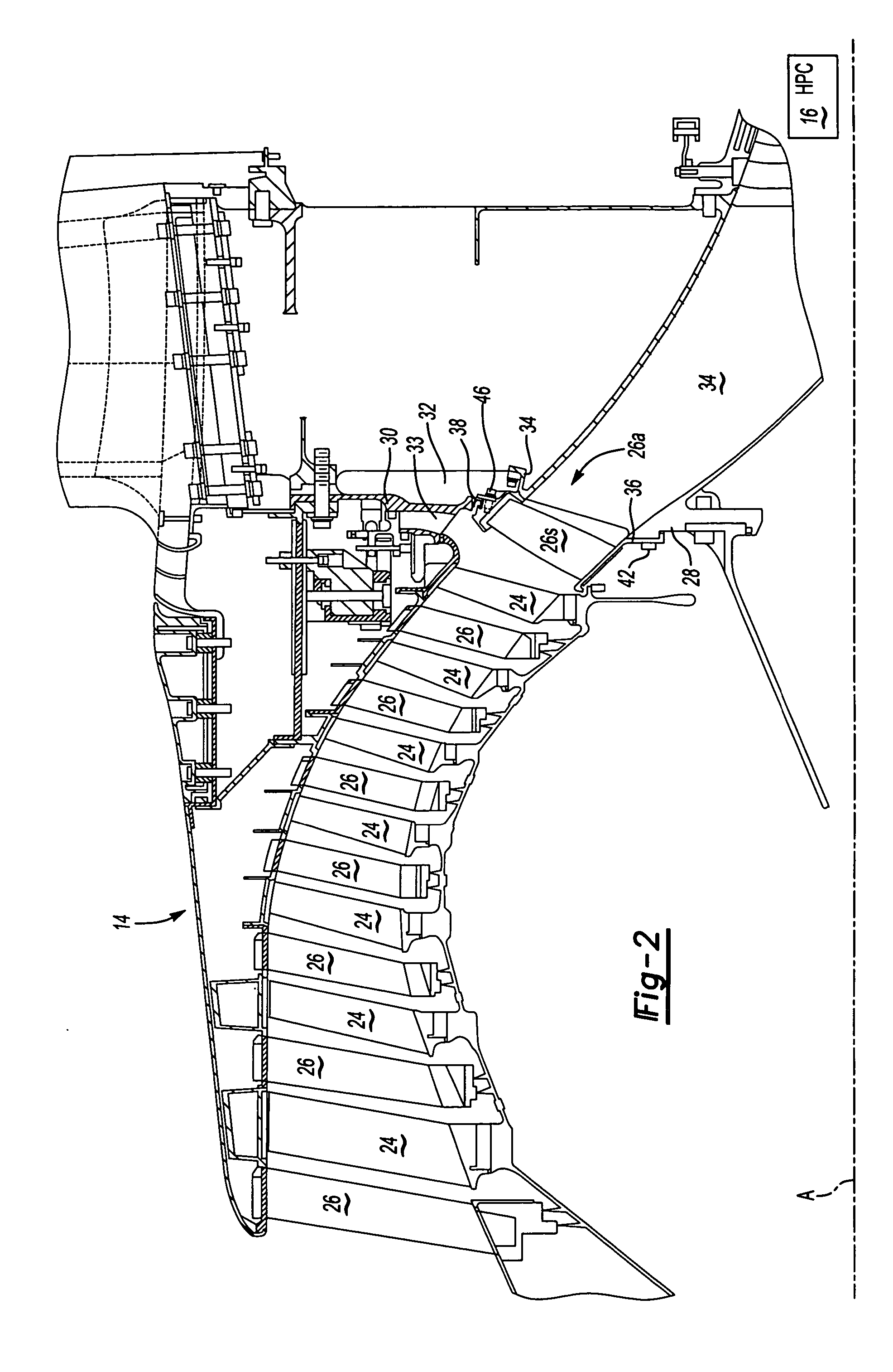
[0017] Referring to FIG. 2, the low pressure compressor section 14 includes alternating rows of rotary airfoils or blades 24 and static airfoils or vanes 26. One vane assembly 26 is a low-pressure compressor (LPC) exit stator assembly 26a also referred to as “4th” stage. It should be understood that although a ...


PUM


Abstract

A low-pressure compressor exit stator assembly for a gas turbine includes a multiple of vanes mounted between a full hoop outer shroud and an inner shroud. The outer shroud and inner shroud are mounted to the intermediate case structure. A seal is located between the outer shroud and a bleed duct structure to accommodate thermal growth mismatch.

Description

BACKGROUND OF THE INVENTION [0001] The present invention relates to a stator assembly, and more particularly to a low-pressure compressor exit stator assembly which interfaces with a full hoop outer shroud pressure vessel within a gas turbine engine. [0002] A gas turbine engine typically includes a rotor assembly which extends axially through the engine. A stator assembly is spaced radially from the rotor assembly and includes an engine case which circumscribes the rotor assembly. A flow path for working medium gases is defined within the case. The flow path extends generally axially between the stator assembly and the rotor assembly. [0003] The rotor assembly includes arrays of rotor blades. The arrays of rotor blades extend radially outward across the working medium flow path in proximity with the case. Arrays of stator vane assemblies are interdergitated with the arrays of rotor blades. The stator vanes extend inward from the case across the working medium flow path into proximit...

Claims


Application Information

Patent Timeline
IPC IPC(8): F01D5/00F01D9/02F01D9/04F01D25/00F04D29/54
CPCF01D9/042F01D25/246F05D2240/55F04D29/542F04D29/644F02C9/18F01D9/02F01D5/00
Inventor SERVADIO, MICHAEL A.RICHARDSON, R. BRIAN
Owner RAYTHEON TECH CORP
Why Eureka
Try Eureka