Tissue shaping device with self-expanding anchors

a tissue and anchor technology, applied in the field of tissue shaping devices with self-expanding anchors, can solve the problems of reducing circulatory efficiency, requiring correction, and rapid deterioration, and achieve the effects of reducing the regurgitation of the mitral valve, minimizing adverse effects, and maximizing therapeutic

Inactive Publication Date: 2005-06-23
CARDIAC DIMENSIONS
View PDF99 Cites 151 Cited by
  • Summary
  • Abstract
  • Description
  • Claims
  • Application Information

AI Technical Summary

Benefits of technology

[0007] We have invented a tissue shaping device, a set of tissue shaping devices and a method that maximize the therapeutic effect (i.e., reduction of mitral valve regurgitation) while minimizing adverse effects, such as an unacceptable constriction of the circumflex artery or other coronary arteries. The tissue shaping device, set of devices and method of this invention enable the user to adapt the therapy to the patient's anatomy.

Problems solved by technology

Regurgitation is a serious, often rapidly deteriorating, condition that reduces circulatory efficiency and must be corrected.
Each of these procedures is highly invasive because access to the heart is obtained through an opening in the patient's chest.
Patients with mitral valve regurgitation are often relatively frail thereby increasing the risks associated with such an operation.
Coronary arteries such as the circumflex artery may cross between the coronary sinus and the heart, however, raising the danger that deployment of the support may limit perfusion to a portion of the heart by constricting one of those arteries.

Method used


Image

  • Tissue shaping device with self-expanding anchors
  • Tissue shaping device with self-expanding anchors
  • Tissue shaping device with self-expanding anchors

Examples


Embodiment Construction

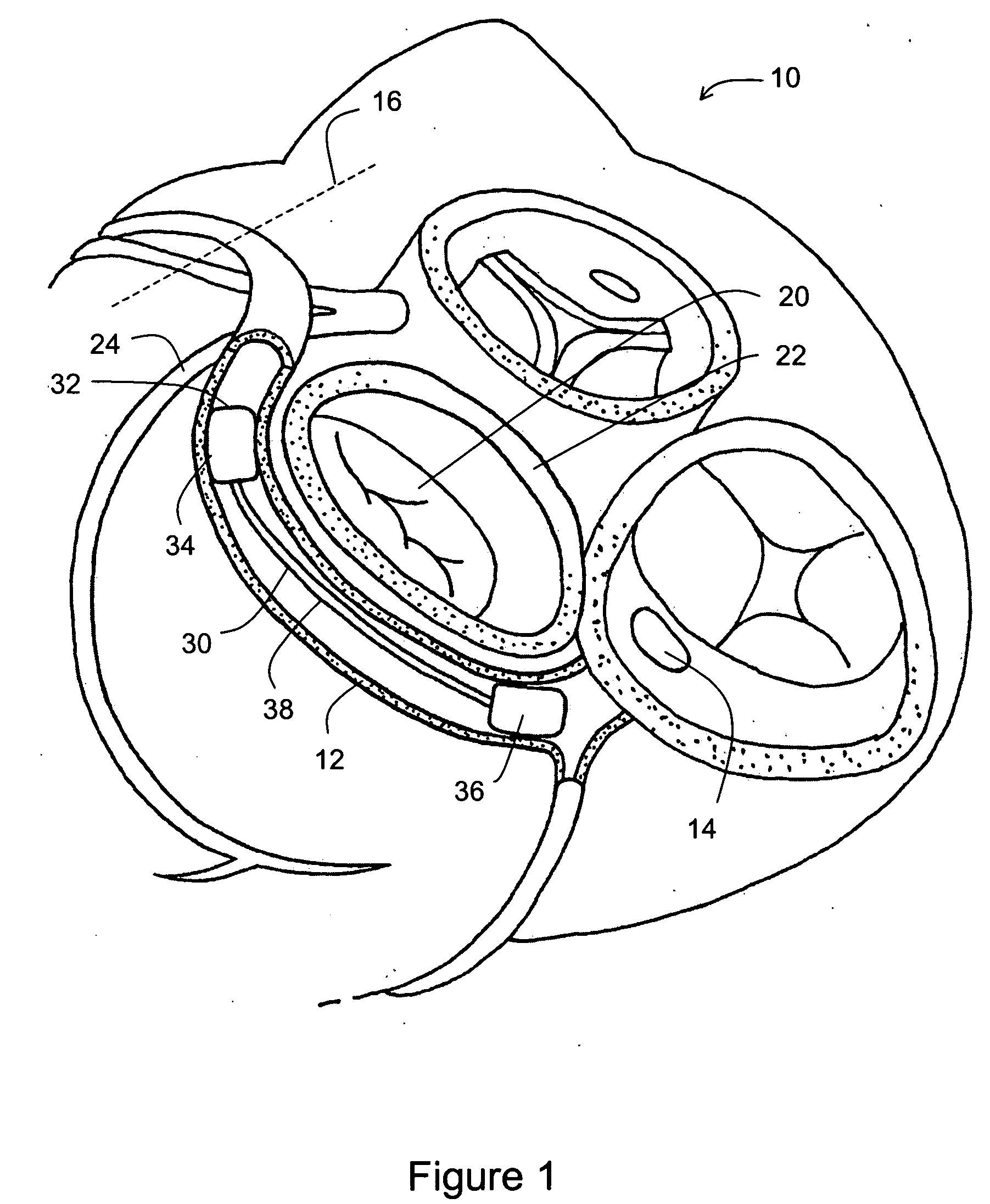
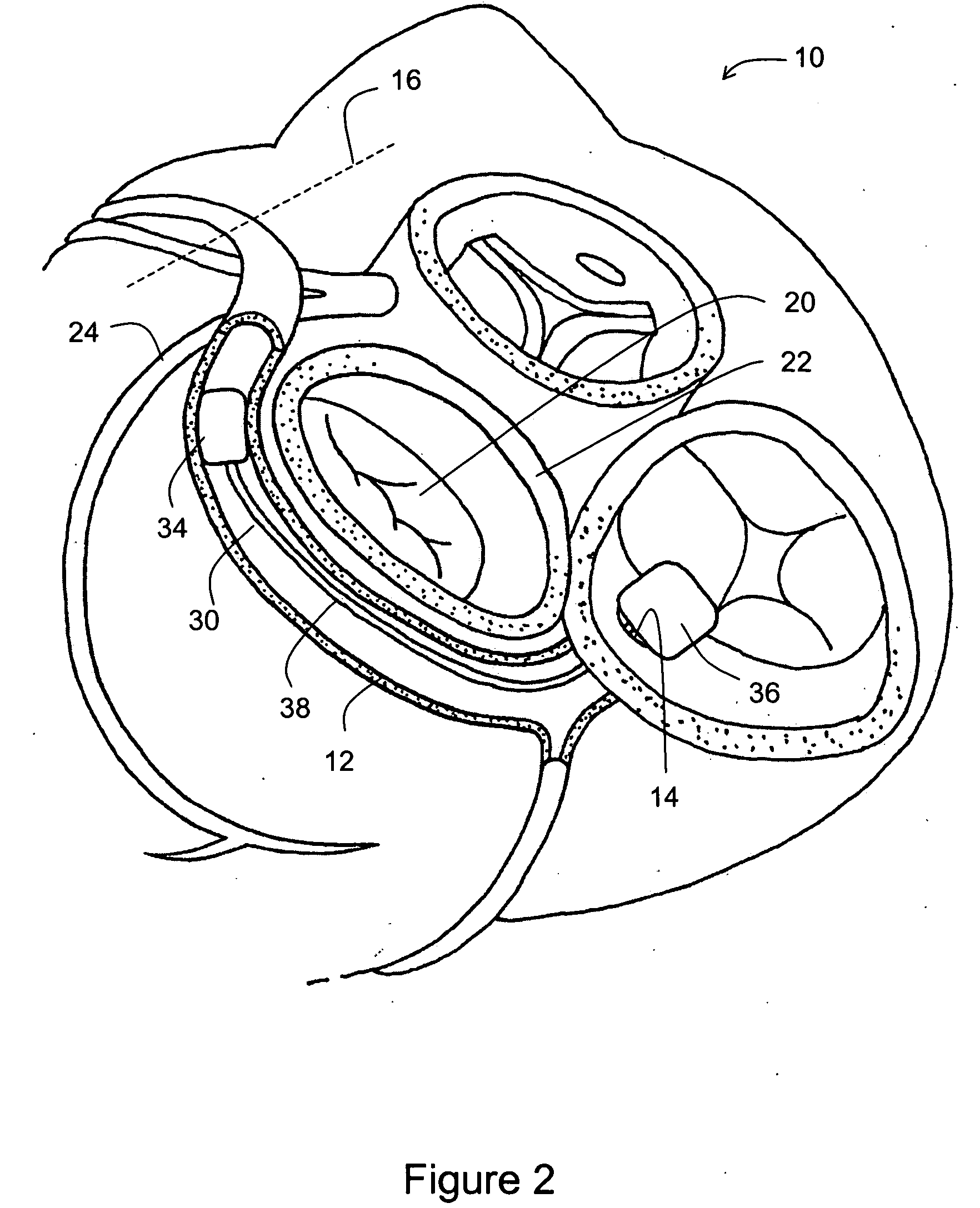
[0044]FIG. 1 shows a partial view of a human heart 10 and some surrounding anatomical structures. The main coronary venous vessel is the coronary sinus 12, defined as starting at the ostium 14 or opening to the right atrium and extending through the great cardiac vein to the anterior interventricular (“AIV”) sulcus or groove 16. Also shown is the mitral valve 20 surrounded by the mitral valve annulus 22 and adjacent to at least a portion of the coronary sinus 12. The circumflex artery 24 shown in FIG. 1 passes between the coronary sinus 12 and the heart. The relative size and location of each of these structures vary from person to person.

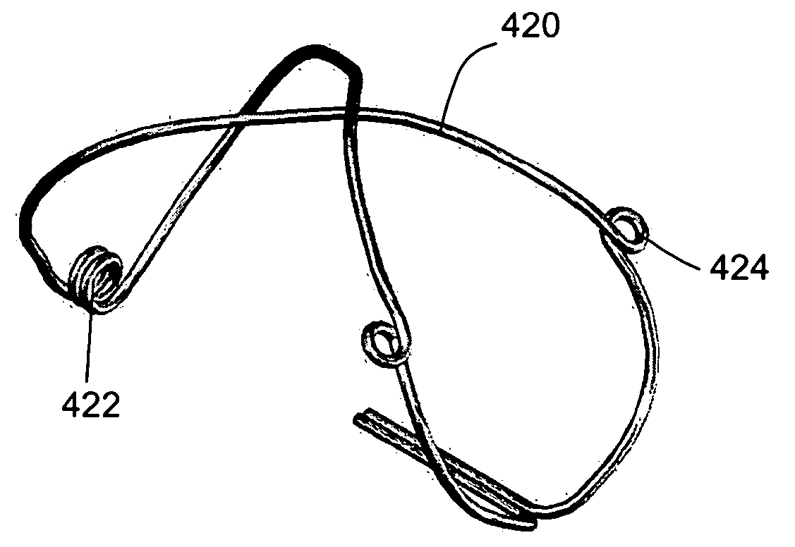
[0045] Disposed within the coronary sinus 12 is a tissue shaping device 30. As shown in FIG. 1, the distal end 32 of device 30 is disposed proximal to circumflex artery 24 to reshape the adjacent mitral valve annulus 22 and thereby reduce mitral valve regurgitation. As shown in FIG. 1, device 30 has a distal anchor 34, a proximal anchor 36 and a c...


PUM


Abstract

A tissue shaping device adapted to be deployed in a vessel to reshape tissue adjacent to the vessel. In some embodiments the device includes a distal anchor having a flexible wire with at least one bending point and first and second arms extending from the bending point, the first and second arms being adapted to deform about the bending point; a proximal anchor having a flexible wire with at least one bending point and first and second arms extending from the bending point, the first and second arms being adapted to deform about the bending point; and a connector disposed between the distal anchor and the proximal anchor.

Description

BACKGROUND OF THE INVENTION [0001] This invention relates generally to devices and methods for shaping tissue by deploying one or more devices in body lumens adjacent to the tissue. One particular application of the invention relates to a treatment for mitral valve regurgitation through deployment of a tissue shaping device in the patient's coronary sinus or great cardiac vein. [0002] The mitral valve is a portion of the heart that is located between the chambers of the left atrium and the left ventricle. When the left ventricle contracts to pump blood throughout the body, the mitral valve closes to prevent the blood being pumped back into the left atrium. In some patients, whether due to genetic malformation, disease or injury, the mitral valve fails to close properly causing a condition known as regurgitation, whereby blood is pumped into the atrium upon each contraction of the heart muscle. Regurgitation is a serious, often rapidly deteriorating, condition that reduces circulator...

Claims


Application Information

Patent Timeline
Patent Type & Authority Applications(United States)
IPC IPC(8): A61F2/04A61F2/24
CPCA61F2/2451
Inventor NIEMINEN, GREGORYBEGET, GARRETTARONSON, NATHANGORDON, LUCAS
Owner CARDIAC DIMENSIONS
Why Eureka
Try Eureka