System and method for metering the performance of a data processing system

a data processing system and performance measurement technology, applied in the field of data processing systems, can solve the problems of exceeding the processing power of the available computer resources, the processing power of the data is not enough, so as to achieve the effect of scaling the performance of the ip

Inactive Publication Date: 2005-06-23
UNISYS CORP
View PDF3 Cites 33 Cited by
  • Summary
  • Abstract
  • Description
  • Claims
  • Application Information

AI Technical Summary

Benefits of technology

[0025] According to the foregoing embodiment, performance of an IP may be scaled using a scaling factor that is derived using one or more lookup tables. These tables contain data indicating the peak performance level that will be provided by any allowable configuration of the data processing system. After the customer selects a configurat...

Problems solved by technology

Many growing businesses are challenged with ensuring that their data processing systems keep pace with expanding demands.
Another challenge facing many businesses is that of predicting and handling the peak loads that will be required to keep up with the day-to-day operations.
For example, if there is a delay in gathering year-end data there may be little time to process the data before the results must be published or otherwise released.
The processing power required to handle such year-end data on such short notice may exceed the processing power of the available computer resources.
In another example, e-commerce servers may experience severe peak loads during certain times of the year, such as the Christmas season.
The extent of these peak loads is also often difficult to predict.
This can be expensive, and is not desirable if the additional systems are only required to address peak loads that exist during relatively short time periods.
However, system updates may necessitate the termination of normal processing activities so that the system can be powered down or otherwise placed i...

Method used


Image

  • System and method for metering the performance of a data processing system
  • System and method for metering the performance of a data processing system
  • System and method for metering the performance of a data processing system

Examples


Embodiment Construction

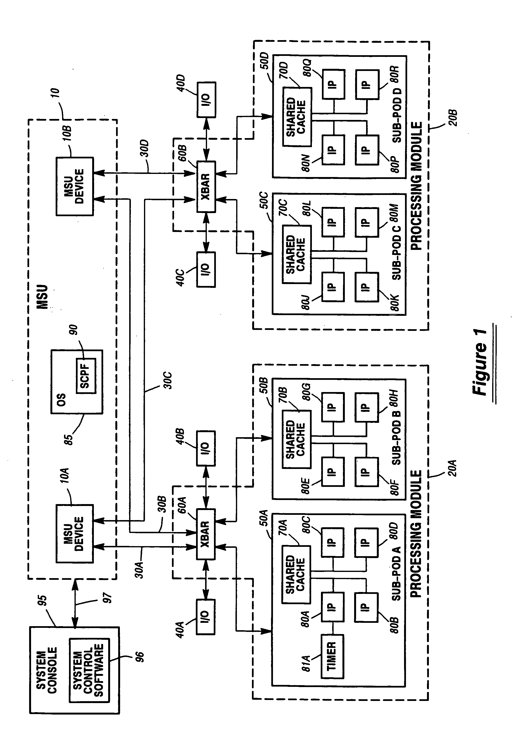
[0048]FIG. 1 is a block diagram of an exemplary system that may employ the current invention. This system includes a Memory Storage Unit (MSU) 10 (shown dashed) which provides the main memory facility for the system. The MSU includes one or more MSU devices individually shown as MSU 10A and MSU 10B, which each contains a predetermined portion of the memory space of the system. Many more MSU devices may be included within a full configuration.

[0049] The system further includes processing modules (PODs) 20A and 20B (shown dashed), which provides the processing capability for the system. A greater or lesser number of PODs may be included in the system than are shown in FIG. 1. In one embodiment, up to four PODs are included in a fully populated system.

[0050] Each of the PODs is coupled to each of the MSU devices via a dedicated, point-to-point connection referred to as an MSU Interface (MI), individually shown as MIs 30A through 30D. For example, MI 30A interfaces POD 20A to MSU devi...


PUM


Abstract

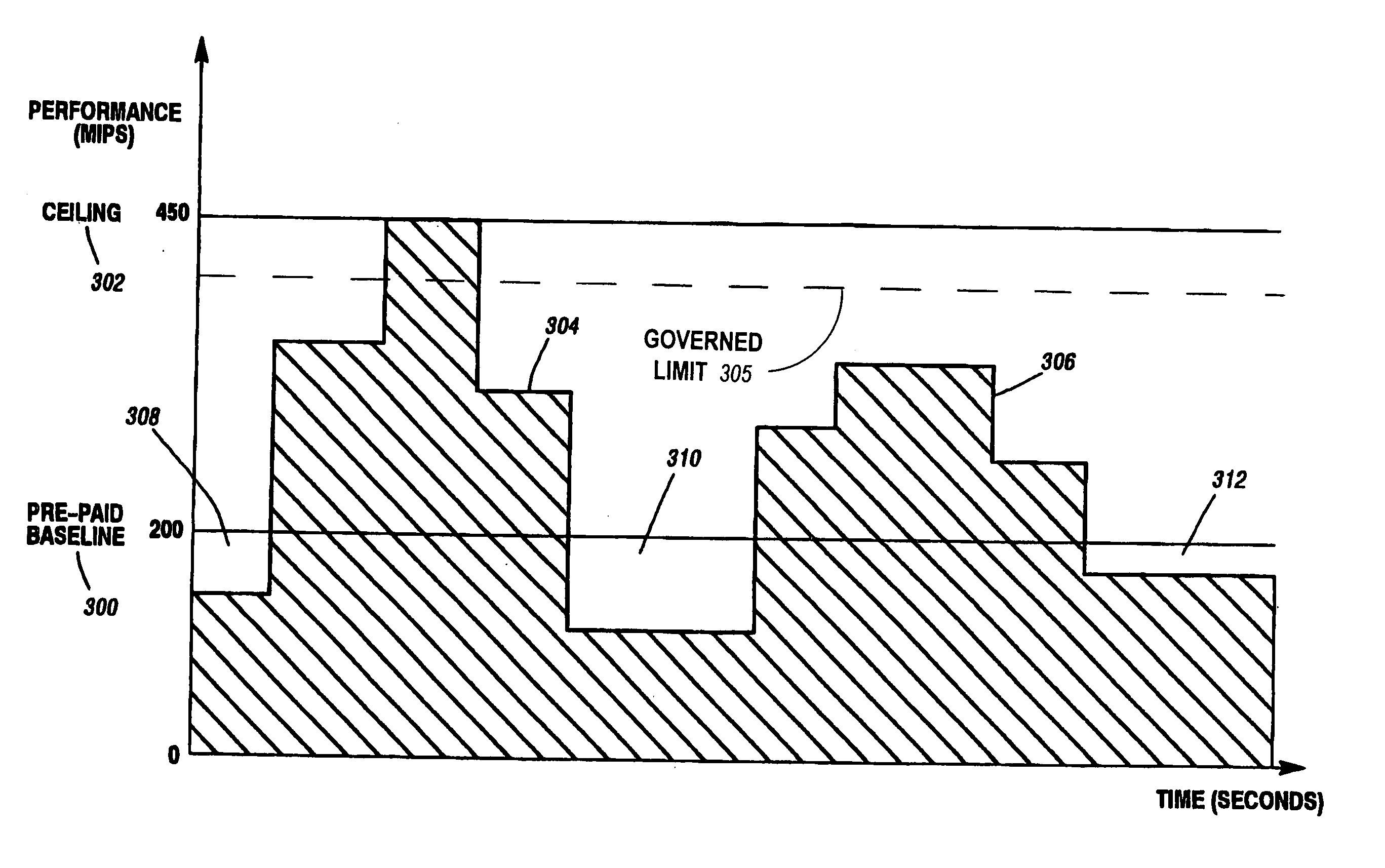
A system and method for metering usage of a data processing system and scaling system performance is disclosed. In one embodiment, an authorization key is purchased that specifies both a baseline performance level and a ceiling performance level. After the key is installed on the data processing system, the system performance level is monitored and averaged over predetermined time periods. The customer is charged on a “pay-as-you-go” basis for any time periods during which the average performance level exceeds the baseline performance level. Performance of the data processing system is not allowed to exceed the ceiling level obtained with the authorization key. In one embodiment, the baseline level may be set to zero so that all performance consumption is purchased by the customer as it is utilized. A report may be generated that includes data upon which analysis of the measured processor utilization data may be performed.

Description

REFERENCE TO CO-PENDING APPLICATIONS [0001] This is a continuation-in-part of U.S. application Ser. No. 10 / 744,685 filed Dec. 23, 2003, entitled “System And Method For Metering The Performance Of A Data Processing System”, attorney docket number RA-5660, and also claims priority from U.S. Provisional Application No. 60 / 557,216 filed on Mar. 29, 2004. [0002] The following commonly assigned co-pending applications have some subject matter in common with the current application: [0003] U.S. application Ser. No. 09 / 676,162 filed Sep. 29, 2000, entitled “Authorization Key System for Selectively Controlling the Performance of a Data Processing System”, attorney docket number RA-5311, which is incorporated herein by reference in its entirety. [0004] U.S. application Ser. No. 10 / 44,660 filed Dec. 23, 2003, entitled “System and Method for Scaling Performance of a Data Processing System”, attorney docket number RA-5639, which is incorporated herein by reference in its entirety. [0005] U.S. ap...

Claims


Application Information

Patent Timeline
IPC IPC(8): G06F15/173
CPCG06F11/3409G06F11/3419G06F11/3438G06Q30/04G06F2201/87G06F2201/885G06F11/3466
Inventor HOFFMAN, PHILIP M.REIST, RANDOLPH C.STELL, JEFFERY A.PARAGAS, JESSICA A.THOMPSON, JAMES W.
Owner UNISYS CORP
Why Eureka
Try Eureka