
Safety tap handle

Active Publication Date: 2005-06-30
CHRISLAN CO ULC
View PDF30 Cites 7 Cited by
  • Summary
  • Abstract
  • Description
  • Claims
  • Application Information

AI Technical Summary

Benefits of technology

[0005] An object of the present invention is to provide a tap handle with a ceramic shell filled with foam, thereby providing a stronger, shard resistant tap handle. The foam filling may be capped by a glue plug.

Problems solved by technology

Ceramic tap handles, although popular, are dangerous as they are brittle, and if struck, tend to shatter into sharp edged shards.
The lack of strength and durability renders current ceramic handles less cost effective and a liability, as injuries to operators or customers may occur when handles break.

Method used


Image

  • Safety tap handle
  • Safety tap handle
  • Safety tap handle

Examples


Embodiment Construction

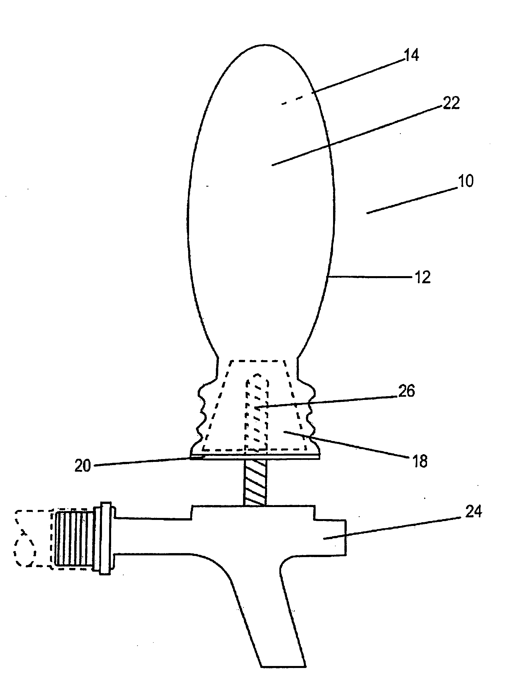
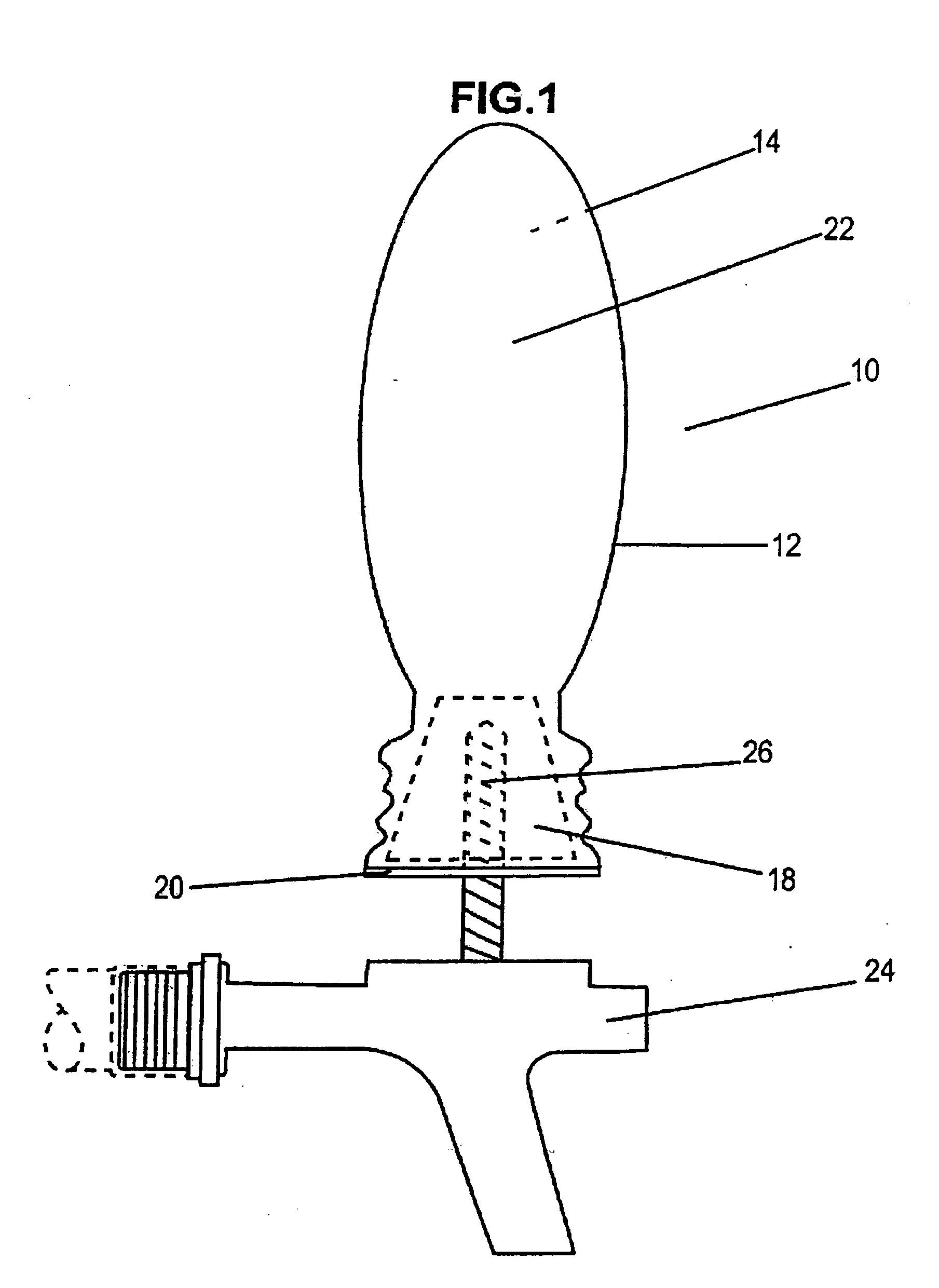
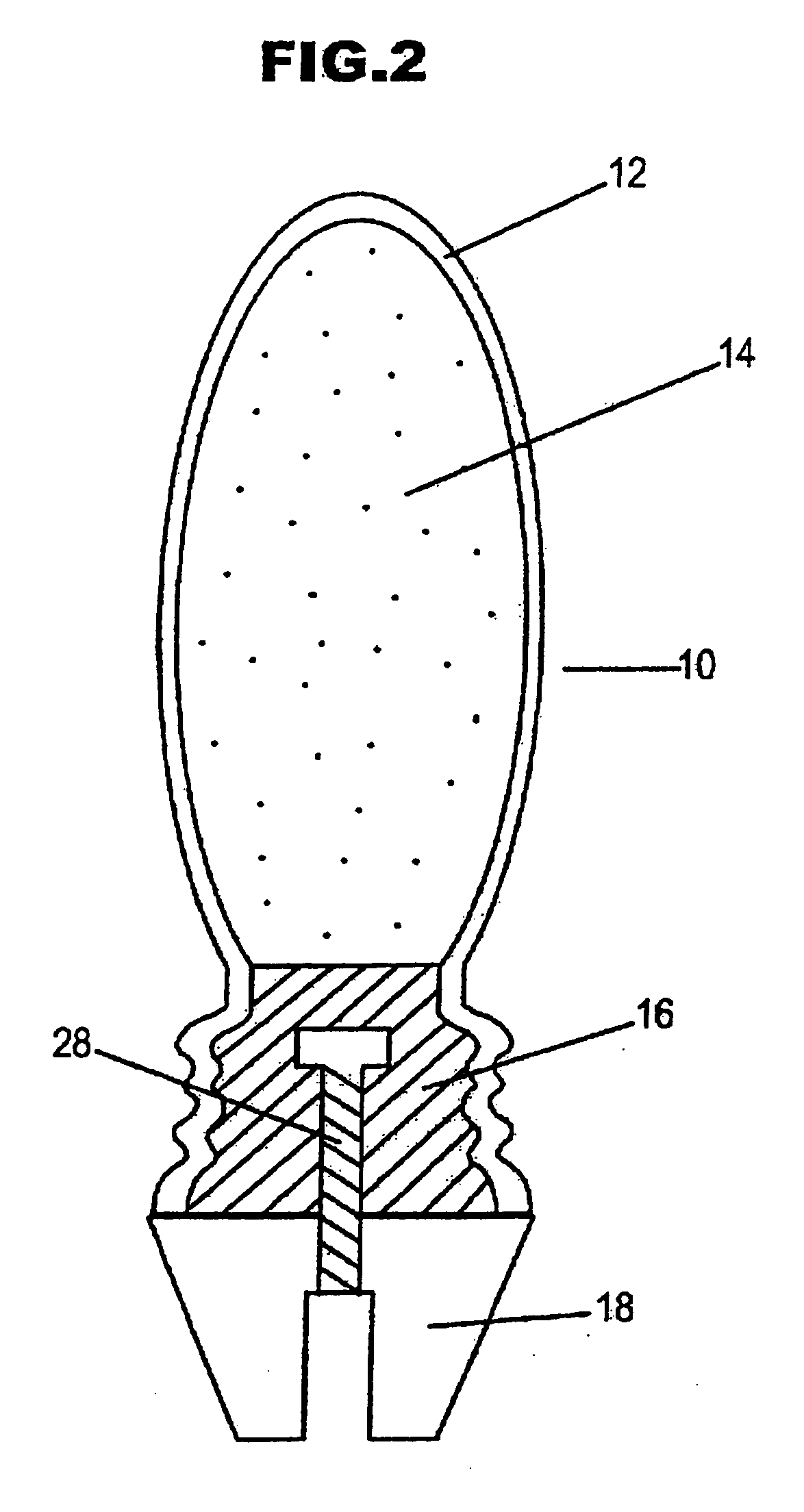
[0011]FIG. 1 depicts an embodiment of the apparatus for an improved safety tap handle 10 used for selectively opening and closing a tap valve on a pressurized beverage system in accordance with the present invention. In general, the tap handle 10 consists of an elongated hollow shell 12 with an open end 11. According to the invention, a hardened foam 14 fills the interior of the shell 12, and the open end 11 is sealed with glue 16 and a threaded ferrule 18. Finally, a plastic cap 20 may be placed on top of the ferrule 18 in the preferred embodiment.

[0012] The tap handle 10 is adapted to screw onto a tap 24. Tap handles 10 are distinctive of the band of beverage being dispensed on the particular tap 24. They, therefore, vary in size, shape and colour and often bear the tradename, trademark and logo of a particular beverage supplier such as a brewery. Tap handles 10 are typically elongated structures usually between 30-60 mm (1.2″-2.4″) in diameter and 200-300 mm (7.9″-12″) in length...


PUM


Abstract

An apparatus is disclosed for a tap handle for beverage dispensing comprising a ceramic, porcelain or stoneware handle filled with a foam, preferably polyurethane foam which renders the tap handle more resilient and resistant to sharding. Ideally, polymeric diphenylmethane diisocyanate foam is injected into a tap handle shell in lquied form, which solidifies and is capped with a glue, an internally threaded cap and a protective plastic cap.

Description

FIELD OF THE INVENTION [0001] The invention relates to beverage dispensing accessories. More particularly, the invention relates to an improved, strengthened ceramic, hardened foam filled tap handle having shatter resistant and resilient safety characteristics. BACKGROUND OF THE INVENTION [0002] Restaurants, bars, pubs and nightclubs and other establishments employ pressurized beverage delivery systems where the flow of the beverage, typically beer, is regulated by a tap. The tap is usually mounted on the bar, and is operated by a tap handle which is rotated forward to open a valve in the tap and pour the beverage into a glass. Various types of taps and valves are used. It has become standard in the industry to display the name and often a logo of the brewer on the tap handle associated with the beverage dispensed from that particular tap. Historically, tap handles have been manufactured from wood, resin, plastic and ceramic. Recently ceramic handles have become popular as a high qu...

Claims


Application Information

Patent Timeline
IPC IPC(8): B67D1/14
CPCB67D1/1477F16K31/607G05G1/06Y10T16/498Y10T16/48Y10T16/506G05G1/08
Inventor LANINGA, ALAN JACK JOHANLANINGA, JACK ANTHONY
Owner CHRISLAN CO ULC
Learn More