Split cascode line amplifier for current-mode signal transmission

a current-mode signal and cascode line technology, applied in the direction of waveguide type devices, gain control, pulse technique, etc., can solve the problems of cable self capacitance, signal carried by the cable is attenuated and distorted, and achieves low cost, low cost and strength. , the effect of high physical strength

Inactive Publication Date: 2005-07-07
GWINN JOSEPH
View PDF15 Cites 5 Cited by
  • Summary
  • Abstract
  • Description
  • Claims
  • Application Information

AI Technical Summary

Benefits of technology

[0019] The present invention relates to a split cascode line amplifier for current-mode signal transmission over a transmission line that has at least two conductors. In accordance with the invention, the split cascode line amplifier permits the use of cables for transmitting analog signals that are chosen based on their relatively low cost and high physical strength. This relieves the necessity to sacrifice the benefits associated with low cost and strength due to the need to choose cables based on their ability to achieve low source loading, transmit high fidelity signals, and eliminate microphonics.
[0020] A key observation has been made that a cascode circuit uses current-mode transmission to carry signals between its first and second amplifying devices. In addition, a cascode circuit can be split into front and back ends that are connected by a cable to take advantage of this observed property. This is possible all while retaining a wide operational bandwidth for which cascode circuits are valued.
[0021] In accordance with the present invention, current-mode transmission is implemented in the split cascode line amplifier in a manner that is a simple and suitable for use in audio systems. Here, the front end includes a first amplifying device, and the back end includes a second amplifying device. In addition, phantom power is implemented, where the back end energizes the front end via the transmission cable. The split cascode line amplifier of the contemplated embodiments permits the implementation of phantom power using the same components that are used to implement current-mode transmission over a cable.
[0022] The split cascode line amplifier of the contemplated embodiments is simple in structure and uses standard electronic components and thus, it is inexpensive to manufacture. The simplicity and low power nature of the front end circuitry also permits it to be powered from the back end via the transmission cable. As a result, a power source, e.g., a battery, is not required in the front end. The simplicity and absence of a battery in the front end permits the split cascode amplifier to fit entirely within the back shell of an ordinary cable connector. This facilitates the use of standard “off-the-shelf” cable connectors. In addition, the front end assembly can be “potted” for enhanced environmental and mechanical resistance, and the signal source does not to be modified. As a result, the cascode circuit of the present invention may be used with a wide variety of signal sources.

Problems solved by technology

A considerable disadvantage and limitation of electrical transmission cables used to carry analog signals is the self capacitance of such cables.
Here, signals carried by these cables tend to be attenuated and distorted to a degree that is determined by the impedances of the source and sink, as well as the length of the cable.
In this case, signals at higher frequencies and signals sent over longer cables suffer a greater level of degradation.
Another disadvantage and limitation associated with transmission cables is that some types of insulation used in the manufacture of such transmission cables have dielectric and absorption constants that vary significantly with frequency, especially at low frequencies.
This causes disturbing distortions that are difficult to eliminate by equalization or the adjustment of tone controls.
Such distortions of signals at low frequencies are particularly caused by dielectric absorption, i.e., soakage.
This is in addition to the previously mentioned signal attenuation and distortion of the signal at high frequencies.
Yet another disadvantage associated with transmission cables is capacitive loading of the signal source by the cable.
This shift causes an overemphasis of the higher harmonics which leads to a harsh sounding instrument.
However, the improvement, although significant, is not sufficient to eliminate the above mentioned problems.
As a result, the length of such cables is greatly limited.
This is achieved at the expense of increased complexity and manufacturing costs.
Also, voltage amplification does not solve the effects of distortion caused by dielectric absorption.
Another disadvantage associated with using electrical transmission cables to carry analog signals is that some transmission cables are themselves microphonic; that is, they respond like microphones and pick up extraneous sounds.
This results in annoying noises that occur when the cables are handled or disturbed.
This is a particular problem during public performances, where it is difficult to avoid disturbing the cables.
As a result, any triboelectric charge which is generated by handling or disturbing the cable is harmlessly drained off.
All practical amplifying devices have undesired parasitic capacitances between their terminals.

Method used


Image

  • Split cascode line amplifier for current-mode signal transmission
  • Split cascode line amplifier for current-mode signal transmission
  • Split cascode line amplifier for current-mode signal transmission

Examples


Embodiment Construction

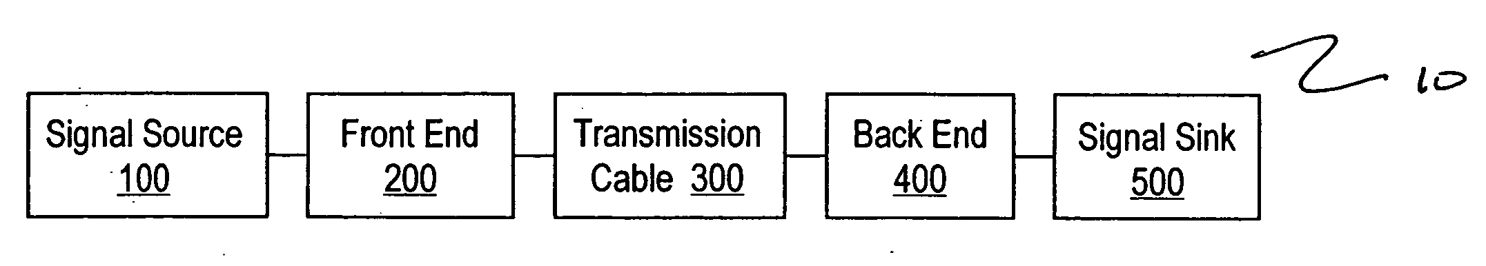
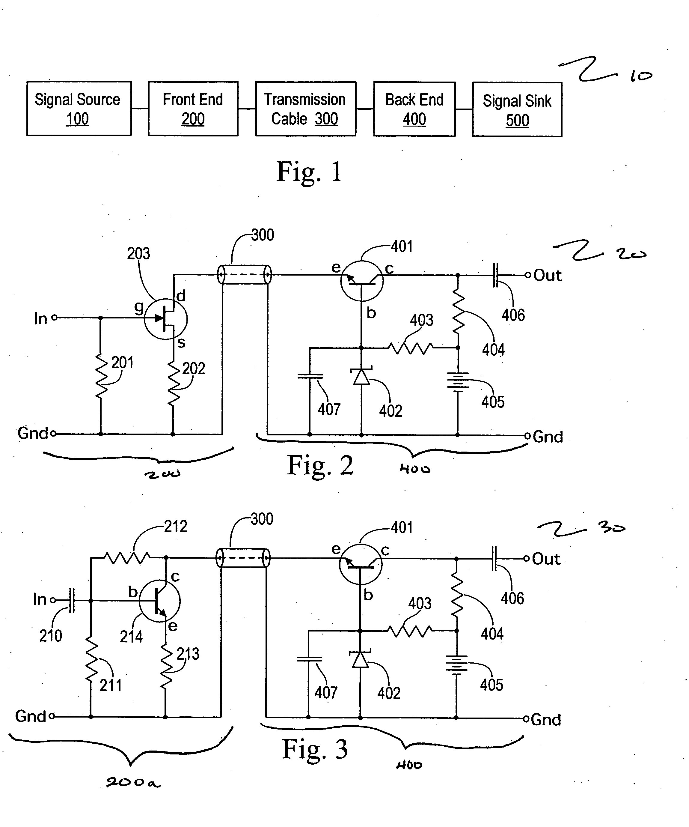
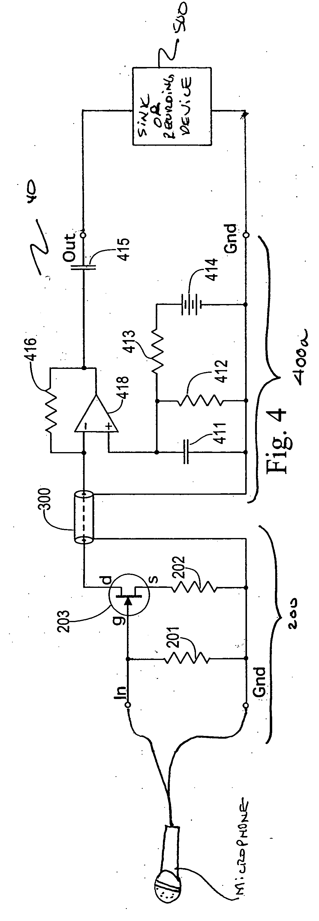
[0028]FIG. 1 is an exemplary schematic block diagram of a split-cascode line amplifier 10 in accordance with the invention. As shown in FIG. 1, a signal originates in the signal source 100. The signal is supplied to the front end 200 and flows through the transmission cable 300 and the back end 400, and terminates in the signal sink 500.

[0029] In the contemplated embodiments of the invention, any source of signals can be used as the signal source. In certain embodiments, the signal source is a transducer. In the preferred embodiment, the signal source 100 is a microphone, an electromagnetic or piezoelectric transducer on a musical instrument, an accelerometer, a low-frequency radio antenna, a hydrophone, a geophone, or the like.

[0030] In conventional systems, the front end 200 can be a voltage amplifier, a transformer, or both, or it can be omitted. In this case, the signal source 100 is connected directly to the transmission cable 300. In accordance with the exemplary embodiments...


PUM


Abstract

Current-mode transmission is implemented in a cascode amplifier by splitting a cascode circuit into a front end and a back end to ensure wideband current-mode transmission of an audio signal. A transmission cable is located between the high impedance output of the first end and the low impedance input of the back end. The front end includes a first amplifying device, and the back end includes a second amplifying device. The front end is phantom powered by the back end using the same electrical conductors that carry the current-mode signal over the transmission cable.

Description

BACKGROUND OF THE INVENTION [0001] 1. Field of the Invention [0002] The present invention generally relates to the high-fidelity transmission of analog signals over electrical transmission cables and, more particularly, to a split cascode line amplifier for current-mode signal transmission. [0003] 2. Description of the Related Art [0004] A considerable disadvantage and limitation of electrical transmission cables used to carry analog signals is the self capacitance of such cables. Here, signals carried by these cables tend to be attenuated and distorted to a degree that is determined by the impedances of the source and sink, as well as the length of the cable. In this case, signals at higher frequencies and signals sent over longer cables suffer a greater level of degradation. [0005] Another disadvantage and limitation associated with transmission cables is that some types of insulation used in the manufacture of such transmission cables have dielectric and absorption constants that...

Claims


Application Information

Patent Timeline
Patent Type & Authority Applications(United States)
IPC IPC(8): H03F1/22H03F3/185H03G3/00H03H7/38
CPCH03F1/22H03F3/1855H03F1/226
Inventor GWINN, JOSEPH
Owner GWINN JOSEPH
Why Eureka
Try Eureka