Selectively altering a fiber height in a pile fabric and apparatus

a technology of fiber height and pile fabric, applied in the field of laser treatment of pile fabrics, can solve the problems of method is very costly in terms of capital investment and operating cost, and prior methods are often unfriendly to the environmen

Inactive Publication Date: 2005-07-14
ICON TEXTILE LASER SYST
View PDF20 Cites 26 Cited by
  • Summary
  • Abstract
  • Description
  • Claims
  • Application Information

AI Technical Summary

Benefits of technology

[0016]FIG. 4 is a side-elevational view showing the fiber shortening within an illuminated area and the original fiber height in an adjacent portion of the pile fabric.

Problems solved by technology

Unfortunately, such methods are very costly in terms of capital investment and operating cost.
In addition, these prior methods are often unfriendly to the environment.
However, in the past, certain technical barriers have often prevented the use of lasers to form graphics on certain fabrics.

Method used


Image

  • Selectively altering a fiber height in a pile fabric and apparatus
  • Selectively altering a fiber height in a pile fabric and apparatus
  • Selectively altering a fiber height in a pile fabric and apparatus

Examples


Embodiment Construction

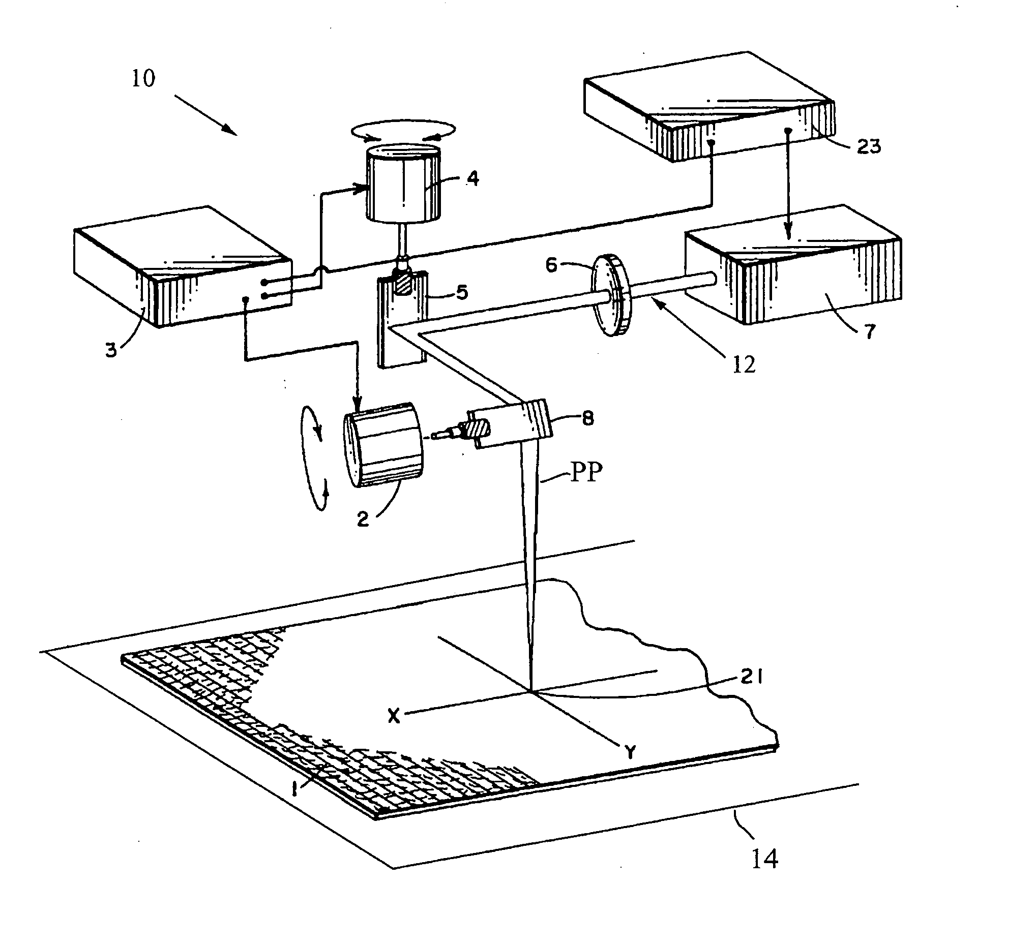
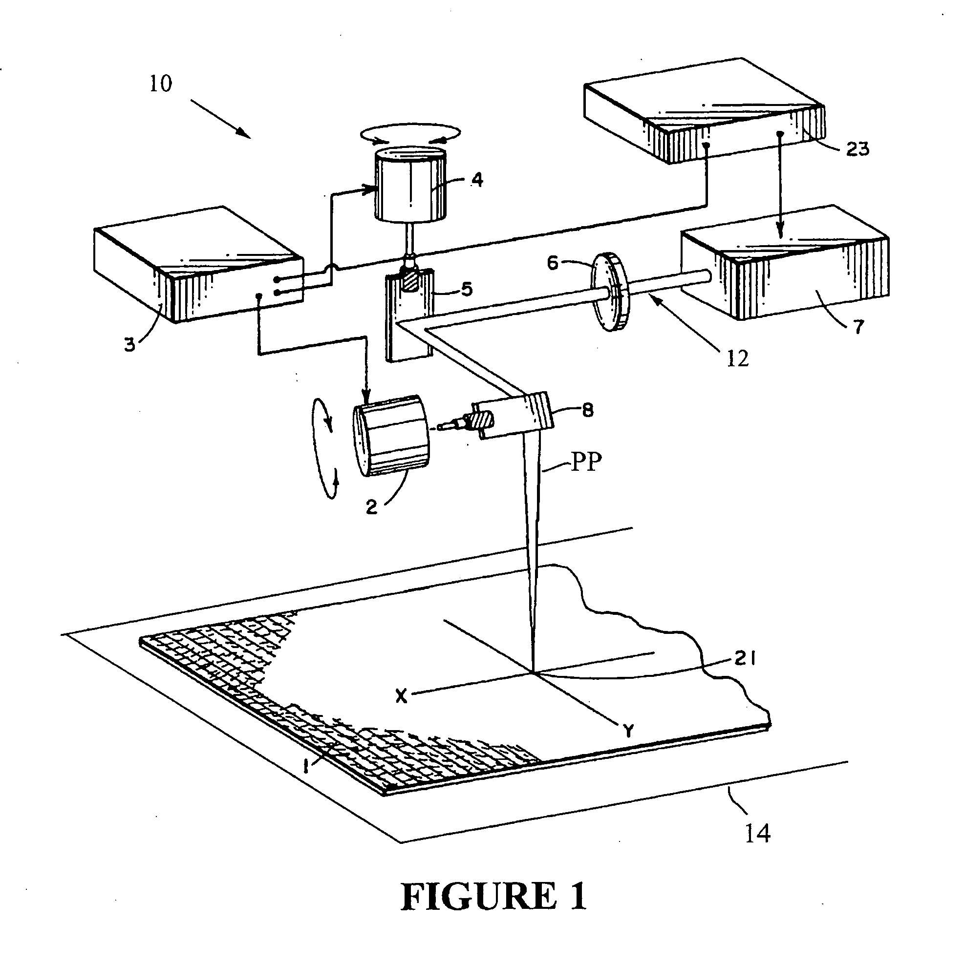
[0017] The laser scanning system 10 projects a laser beam 12 along a projection path PP to intersect the pile fabric 1 being processed as the pile fabric is disposed upon a pallet 14.

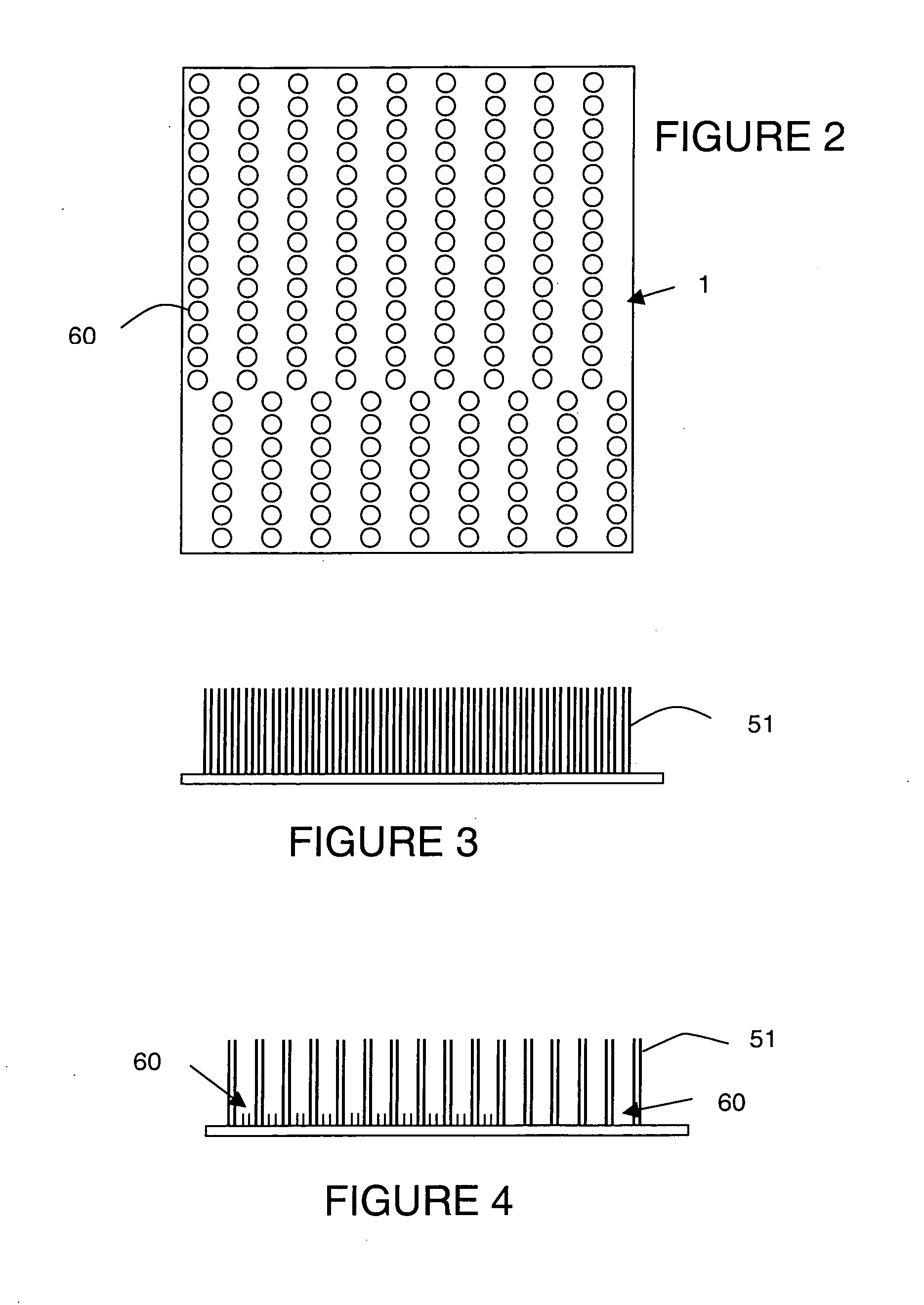
[0018] The laser scanning system 10 finds particular application in treating pile fabrics 1. For purposes of description, the term “pile fabric” encompasses textiles and materials made from fibers or threads by weaving, knitting, felting, or other interconnecting processes. The fabric is preferably napped or pile, having a multitude of projecting fibers 51. In the napped fabric, the fibers are typically raised by brushing the fabric to locate the fibers projecting from the fabric, wherein the fibers can be in a loop configuration or have a terminal free end. In the pile configuration, the raised surface is typically produced by fiber loops on the body or substrate of the fabric, wherein the loops are sheared or cut. For purposes of description, the term “pile” includes projecting fibers formed by shear...


PUM

PropertyMeasurementUnit
heightaaaaaaaaaa
heightaaaaaaaaaa
heightaaaaaaaaaa

Abstract

A region of a pile fabric is impacted with a laser at spaced illuminated areas in a dithered image, wherein the laser energy and duration of impact in the illuminated areas are selected to shorten the fibers within the illuminated area. The spacing of the illuminated areas within the region and the amount of shortening within the illuminated areas are selected to essentially maintain a hand or feel of the pile fabric. Fleece and corduroy can be sculpted to provide a three-dimensional image, while maintaining the hand of the fleece. In dyed pile fabrics, the illuminated areas can be selected to change the dye distribution within the pile material to provide an altered coloration.

Description

CROSS-REFERENCE TO RELATED APPLICATIONS [0001] Not applicable. STATEMENT REGARDING FEDERALLY SPONSORED RESEARCH OR DEVELOPMENT [0002] Not applicable. REFERENCE TO A “SEQUENCE LISTING”[0003] Not applicable. BACKGROUND OF THE INVENTION [0004] 1. Field of the Invention [0005] The present invention relates to laser treating pile fabrics and, more particularly, to changing a fiber height in the pile fabric by laser energy, while maintaining a desired feel or hand of the fabric, wherein selected fabrics can exhibit color alteration. [0006] 2. Description of Related Art [0007] Materials have commonly been used to make clothing, linens, footwear, belts, purses and wallets, luggage, vehicle interiors, furniture coverings, wall coverings, and many other manufactured goods. Consumer demand for graphics on these materials has increased over the recent years. Consumers often desire graphics on these materials to give the materials a unique and attractive appearance. [0008] The typical methods of...

Claims


Application Information

Patent Timeline
Patent Type & Authority Applications(United States)
IPC IPC(8): B29C59/16D06C23/00
CPCB29C59/16B29C2791/009D06C23/00B29L2031/7652B29L2031/765D06C13/00D06C23/02
Inventor LATOS, GEORGE P.SHAFFER, WAYNE K.
Owner ICON TEXTILE LASER SYST
Why Eureka
Try Eureka