Variable angle cutting block

a cutting block and variable angle technology, applied in the direction of surgical saws, non-surgical orthopedic devices, osteosynthesis devices, etc., can solve the problems of creating additional work for surgeons, cutting guide surfaces need to be realigned, and process not often providing perfect cuts

Active Publication Date: 2005-07-14
HOWMEDICA OSTEONICS CORP
View PDF26 Cites 99 Cited by
  • Summary
  • Abstract
  • Description
  • Claims
  • Application Information

AI Technical Summary

Problems solved by technology

However, occasionally after the block is fixed to bone, the surgeon realizes that the cutting guide surface needs to be realigned.
This angle must be determined prior to making the proximal tibial cut, as an improper angle will prevent proper balancing of the knee joint.
One option

Method used


Image

  • Variable angle cutting block
  • Variable angle cutting block
  • Variable angle cutting block

Examples


Embodiment Construction

[0020] In describing the preferred embodiments of the subject matter illustrated and to be described with respect to the drawings, specific terminology will be resorted to for the sake of clarity. However, the invention is not intended to be limited to the specific term so selected, and is to be understood that each specific term includes all technical equivalence which operate in a similar manner to accomplish a similar purpose.

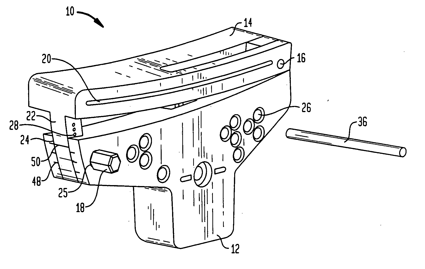
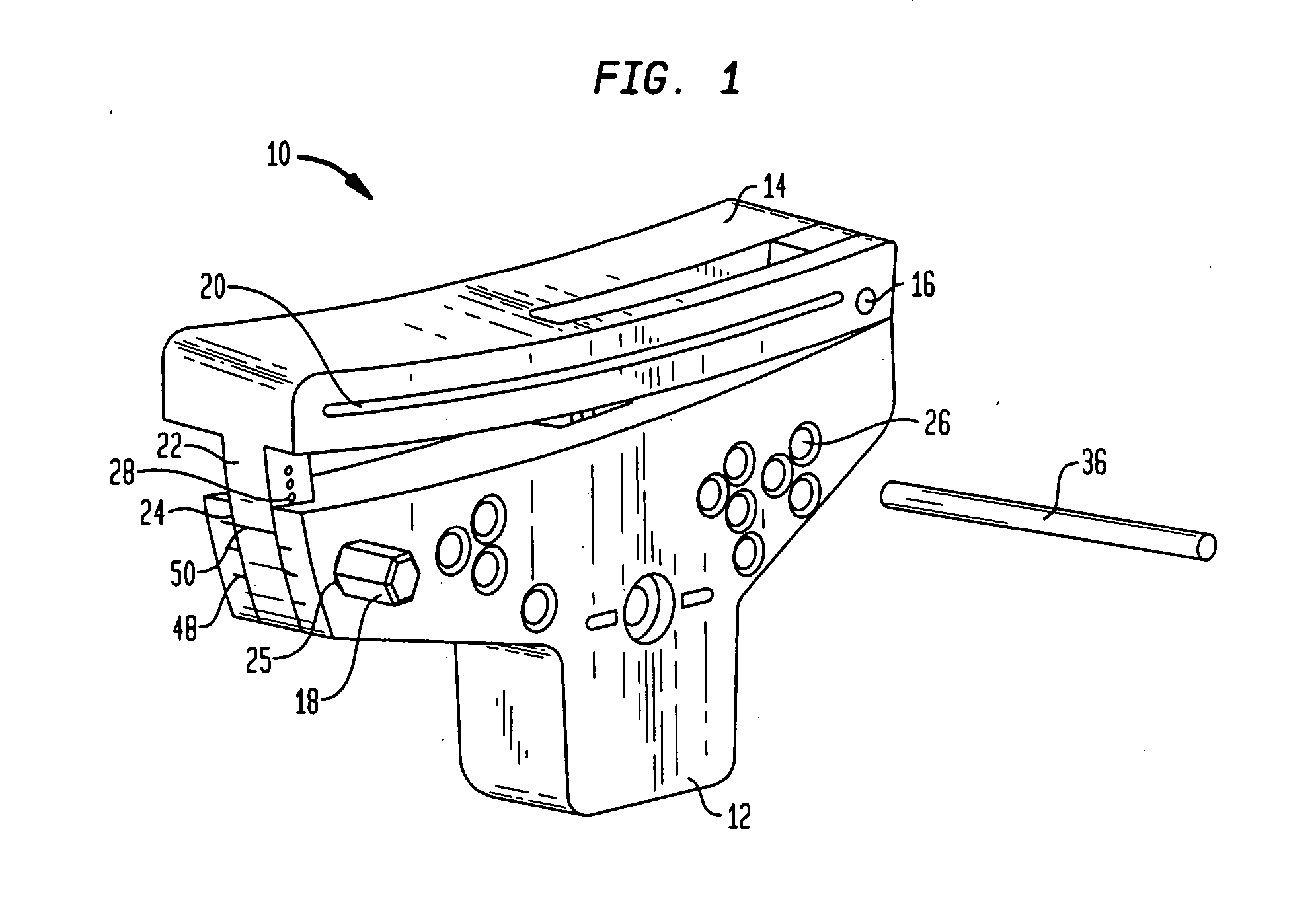
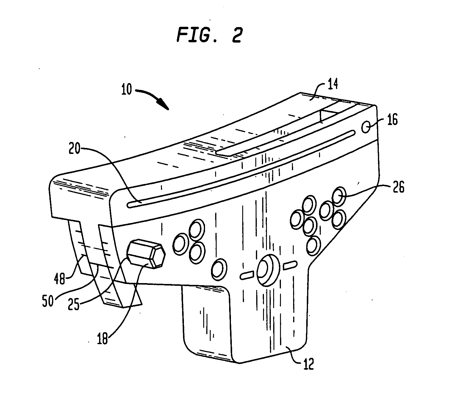
[0021] Referring to the drawings, wherein like reference numerals represent like elements, there is shown in FIGS. 1-4, in accordance with a preferred embodiment of the present invention, an adjustable bone resection guide, or variable angle cutting block, designated generally by reference numeral 10. In a preferred embodiment, cutting block 10 includes a first portion 12, a second portion 14, and screw 18. When the cutting block 10 is used on the tibia, second portion 14 is adjacent the proximal tibia. As shown in FIG. 1, first portion 12 and second portio...


PUM


Abstract

A variable angle cutting block and method for resection a bone are disclosed. The variable angle cutting block comprises a first portion, a second portion, and an angle adjustment system for positioning the first and second portions at a relative angular position upon rotation of the second portion with respect to the first portion. The present invention is useful in allowing for realignment of a cutting guide surface so that a bone cut can be made at a proper varus/valgus angle.

Description

FIELD OF THE INVENTION [0001] The present invention relates to an apparatus and method for resecting a bone surface, and more particularly, to an apparatus and method for resecting the proximal end of the tibia during a total knee arthroplasty. BACKGROUND OF THE INVENTION [0002] As with any successful total knee arthroplasty, proper balancing of the knee joint is of the utmost importance. This balancing is achieved primarily through proper distal femoral and proximal tibia resections or cuts, and to a lesser extent, soft tissue release surrounding the joint capsule. [0003] In order to produce accurate distal femoral and proximal tibial cuts, surgeons use various forms of cutting blocks. The cutting blocks, as useful a tool as they are, still need to be properly positioned by the surgeon. Once properly positioned, the cutting block is fixed to the bone so that a cutting guide surface, usually a saw guide surface, is in correct alignment for performing the required bone resection. How...

Claims


Application Information

Patent Timeline
IPC IPC(8): A61B17/15A61B17/58
CPCA61B17/157A61B17/155
Inventor MICHALOWICZ, JOSEPH JOHN
Owner HOWMEDICA OSTEONICS CORP
Why Eureka
Try Eureka