Massager and massaging method

a technology of massaging method and massage needle, which is applied in the field of massage needle, can solve the problems of insufficient massaging effect on the leg, difficult to massage the whole leg sufficiently, and large differences in the configuration of the leg between individuals, and achieve the effect of easy giving of rolling pressure and smooth rolling pressur

Inactive Publication Date: 2005-07-21
SAKAMOTO FUMIE +4
View PDF13 Cites 35 Cited by
  • Summary
  • Abstract
  • Description
  • Claims
  • Application Information

AI Technical Summary

Benefits of technology

The patent describes a device that can apply smooth pressure to an arm or leg by adjusting the distance between rollers and the configuration of the arm or leg. This device allows for easy and effective pressure therapy for arm or leg injuries.

Problems solved by technology

The technical problem addressed in this patent is how to create a more effective and convenient massager for applying a massage to the arms and legs of users, allowing them to easily adjust the position of the stay components to match different shapes of the limbs being massaged, while also providing sufficient pressure through multiple rollers to achieve optimal results. Additionally, the new design should enable users to comfortably relax and perform the massage exercise without having their body posture significantly affected by the device.

Method used


Image

  • Massager and massaging method
  • Massager and massaging method
  • Massager and massaging method

Examples


example 1

PRACTICAL EXAMPLE 1

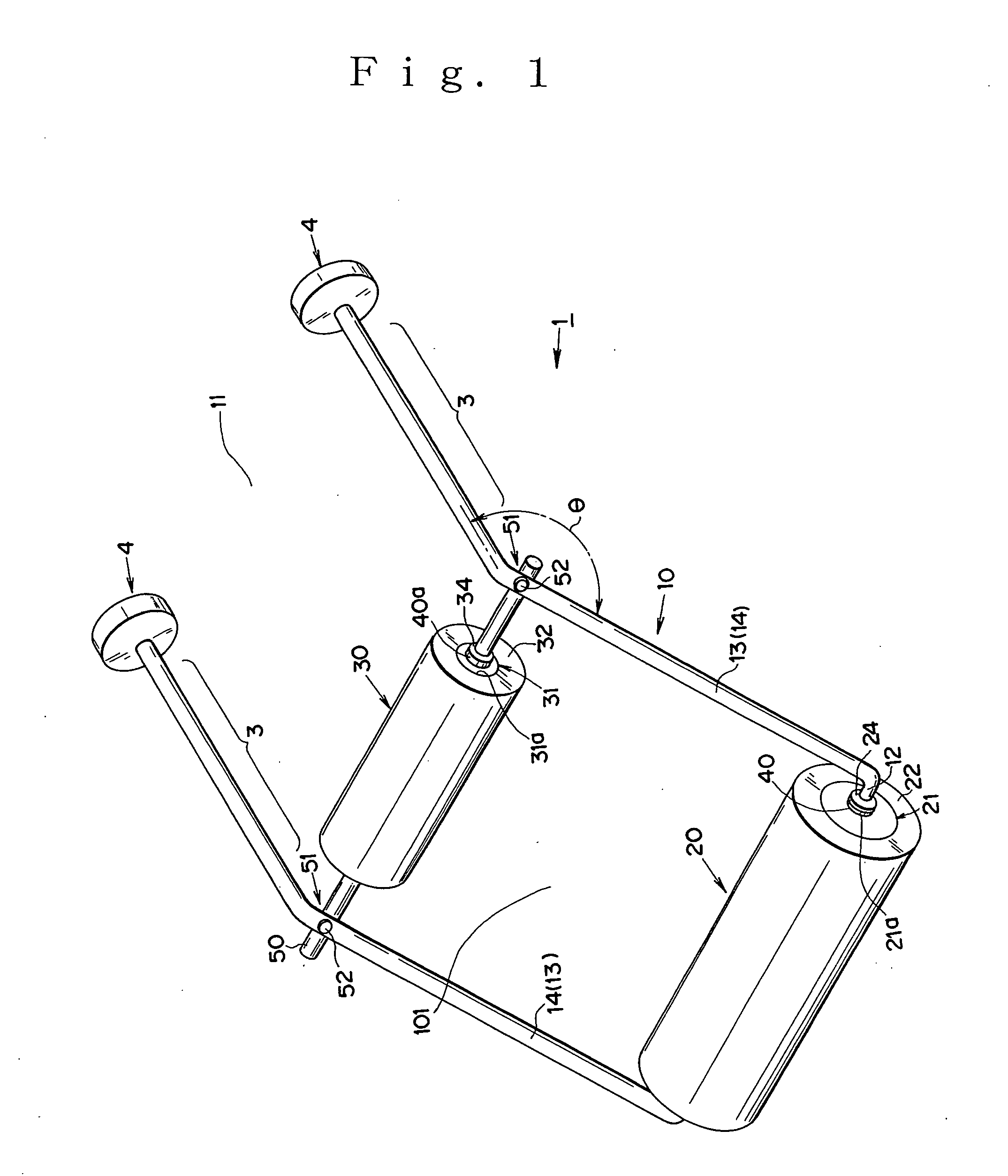
[0173] In the massager 1 shown in FIG. 1, the stay member 1 is made of a stainless steel pipe having a diameter of 5 mm, and similarly, the connection bar 50 is made of a stainless steel pipe having a diameter of 5 mm.

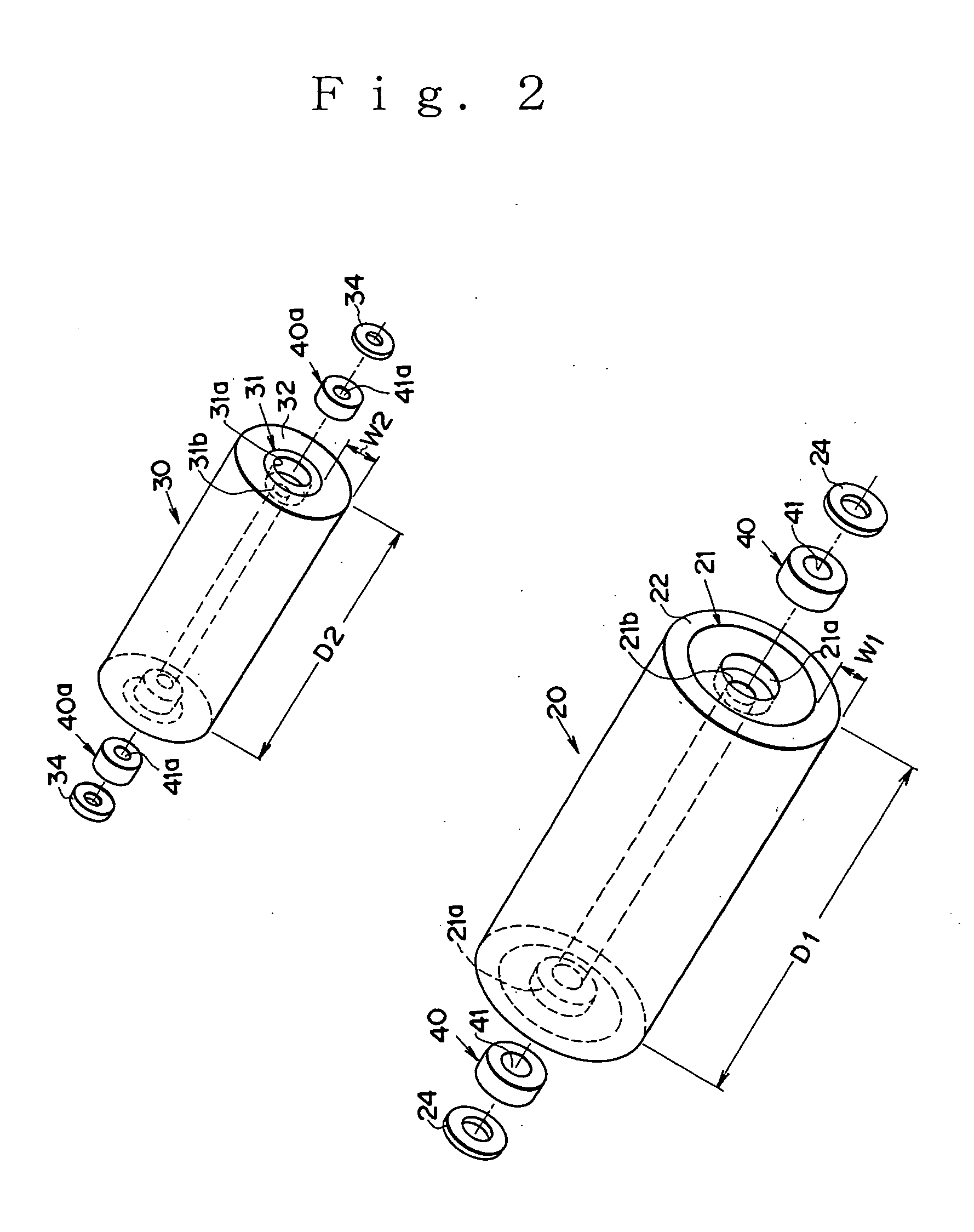
[0174] The roller main body 21 of the first roller 20 is made of wood and has a diameter of 30 mm and a width of about 150 mm. The protection member 22 covering the roller main body 21 is made of urethane or rubber with a penetration rate of about 100 and has a thickness of about 5 mm. The second roller 30 is made of the same material as the first roller 20 and comprises the roller main body having a diameter of about 15 mm, which is covered with the protection member with different penetration rate of about 80 from that of the first roller 20 and has a thickness of about 17 mm. In the center portions of the roller main bodies, there are bored center holes 21b and 31b for receiving the stay member 10 and the connection bar 50, respectively. At the e...

example 2

PRACTICAL EXAMPLE 2

[0179] The massager 1f shown in FIG. 17 is different in configuration from that of the foregoing first Practical Example 1 and has the stays 10b and 10c, operating part 3 and handle 4a made of polycarbonate. The massager could be made light because the first and second rollers 20a and 30a are the same as those in the foregoing embodiment (9) and the extension adjusting mechanism 70a is made of thermoplastic resin or thermosetting resin as well as the stay 10b and the other parts.

[0180] The stay 14b has a width d3 of about 11 mm, and the hollow H for receiving the stay 14b has an inner diameter of about 11 mm equal to the width d3 of the stay. To secure the strength of the hollow H, the stay 14a has an outer diameter d4 of about 17 mm so as to assure a 3 mm thickness wall forming the hollow.

[0181] The insertion hole 4b formed between the operating part 3 and the handle 4a is formed in a trapezoid shape having a longitudinal length L′ of about 50 mm and a short si...

example 3

PRACTICAL EXAMPLE 3

[0186] The massager 100 shown in FIG. 22 comprises the stay 110 made of stainless steel pipe having a diameter of about 5 mm.

[0187] The roller main body 121 of the roller 120 is made of a wood rod having an outer diameter of about 30 mm and a length of about 160 mm. The protection member 122 covering the roller main body 121 is made of an elastic rubber or urethane sheet having a thickness of about 10 mm and a penetration rate of about 80. In the center portions of the roller main body 121, there are formed center holes 121a for accommodating the bearings 150 each having an outer diameter of about 15 mm.

[0188] Each of the running wheels 130 is formed of a wood circular disc having a thickness of about 10 mm and an outer diameter of about 65 mm and has a center hole 131a for accommodating the bearing 151 having a diameter of about 10 mm.

[0189] Thus, the massager 100 has the roller 120 and the running wheels 130 mounted rotatably independently as shown in FIG. 23...


PUM


Abstract

This invention relates to a massager and a massing method. There has been known a conventional leg massager described in Japanese Utility Model Registration No. 3043777. However, there are great differences between individuals in their configurations of the legs, i.e. the above-knee and below-knee parts. Specifically, the shape of the leg portion from ankle to calf of leg differs greatly in individuals, the conventional massager has suffered a disadvantage such that it is difficult to massage the whole leg sufficiently with a single roller and the work becomes onerous where changing the roller in accordance with the shape of the leg. In the light of the foregoing disadvantages of the conventional massager, the present invention was made to provide a massager comprising stays connecting a plurality of rollers, and operating parts extending longitudinally from the stays. With the massager, a massage can be applied to the arm or leg of a user by handling the operating parts extending so as to incline the stays for adjusting the inclination of the stays, consequently to allow the rollers to conform to the shape of the arm or leg and exert massaging pressure on the arm or leg while rotating the rollers along the arm or leg without weakening the massaging pressure. Thus, the massage can be given to the entire aim and leg of the user in an unrestrained operation without restricting the posture of the user being massaged with the massager. In order to solve all of the conventional problems imposed by the conventional massagers, according to the present invention there is provided a massager comprising stays, operating parts formed on the stays, and roller means comprising a plurality of rollers, which are rotatably supported by the stays for holding an arm or leg between the rollers and adjustable in distance therebetween by handling the operating parts to change the inclination of the stays. That is, smooth rolling pressure can readily be given to the arm or leg by handling the operating parts to allow the rollers to conform to the configuration of the arm or leg and rotating the rollers along the arm or leg held between the rollers, while varying the inclination of the stays to adjust the distance between the rollers.

Description


Claims


Application Information

Patent Timeline
Owner SAKAMOTO FUMIE
Why Eureka
Try Eureka