Deflection yoke and cathode ray tube unit

Inactive Publication Date: 2005-07-28
PANASONIC CORP
View PDF6 Cites 0 Cited by
  • Summary
  • Abstract
  • Description
  • Claims
  • Application Information

AI Technical Summary

Benefits of technology

[0010] In view of the above-mentioned problems, the present invention aims to compensate for the variation in the magnetization caused by the individual difference of the permanent magnets, and further to provide a deflection yoke as well as a CRT apparatus provided with the deflection yoke which maintain proper correction of the raster distortion against temperature change of the apparatus.

Problems solved by technology

In the deflection yoke, the magnetization of the magnet decreases in response to an increase in temperature, which results in an overall decrease in the magnetic field lines running out of the magnet.

Method used


Image

  • Deflection yoke and cathode ray tube unit
  • Deflection yoke and cathode ray tube unit
  • Deflection yoke and cathode ray tube unit

Examples


Embodiment Construction

[0047] A CRT apparatus 1 is given below by way of example to illustrate the best embodiment of the present invention.

(1) Overall Structure of the CRT Apparatus 1

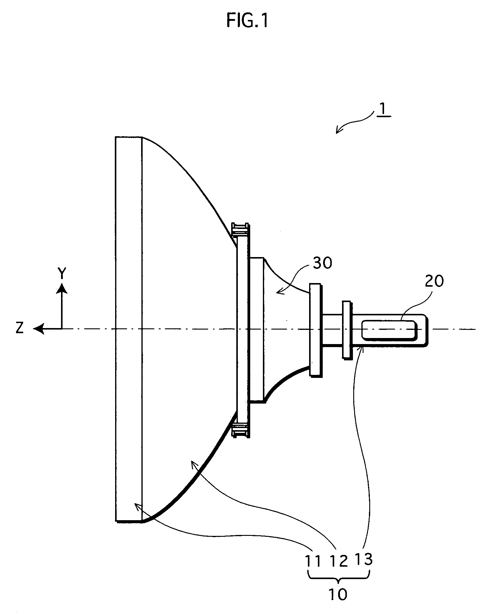
[0048] The overall structure of the CRT apparatus 1 is described by the aid of FIG. 1. FIG. 1 is a side view of the CRT apparatus 1 with selected main components thereof.

[0049] As shown in FIG. 1, the CRT apparatus 1 has an air-tightened container, the CRT 10, and a deflection yoke 30 set on the periphery of the CRT 10. The CRT 10 is composed of a panel 11 with a phosphor screen (not shown) provided inside; a neck 13 where an electron gun 20 is mounted; and a funnel 12 jointing the panel 11 and the neck 13.

[0050] The electron gun 20 is an inline gun and comprises firing units for three electron beams of blue (B), green (G), and red (R).

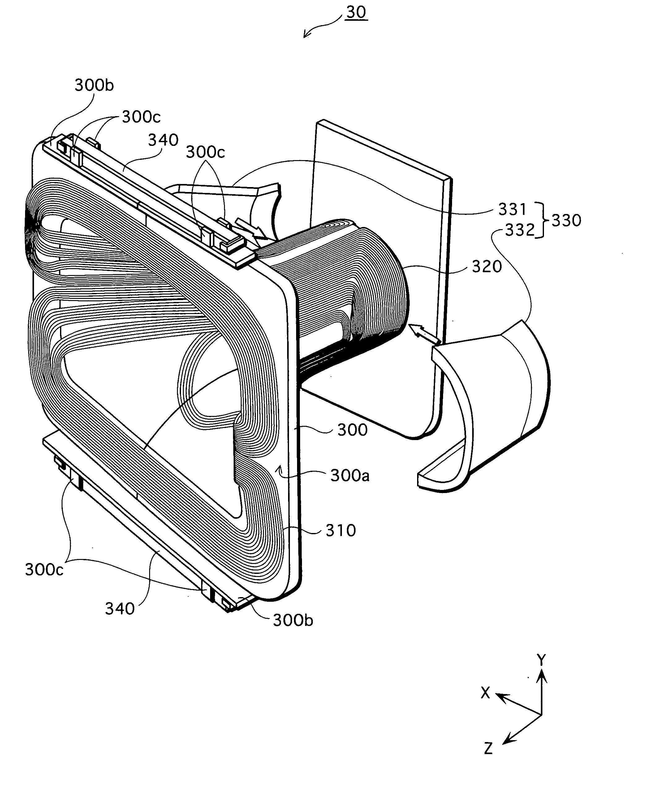
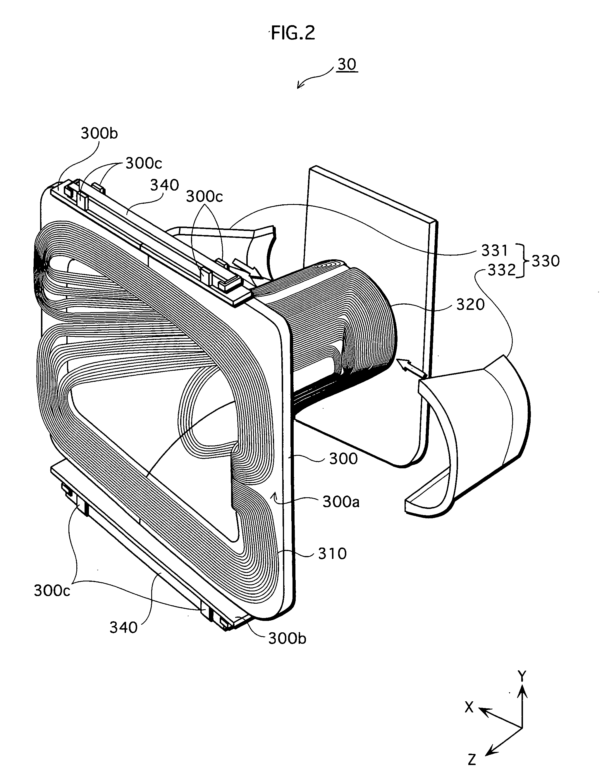
[0051] The deflection yoke 30, whose structure is described later, is placed in the space between the funnel 12 and the neck 13 of the CRT 10 so as to follow the periphery of these two.

...


PUM


Abstract

The present invention aims to compensate for the variation in the magnetization of permanent magnets caused by the individual difference, and further to provide a deflection yoke and a CRT apparatus provided with the deflection yoke which maintain proper correction of raster distortion against temperature change of the apparatus. To accomplish these objects, in a correction unit 340 provided with the deflection yoke 30 of the CRT apparatus 1 according to the present invention, a magnetic substance 342 having an attribute in which its permeability changes with a negative temperature characteristic is attached to a permanent magnet 341 so as to cover at least one of both end faces 341a and 341b. Additionally, in the deflection yoke 30, a paired correction units 340 is symmetrically placed at the top and the bottom of the deflection yoke, opposite to each other in respect to the tube axis of the CRT 10.

Description

TECHNICAL FIELD [0001] The present invention relates to a deflection yoke and a cathode-ray tube apparatus, and especially relates to a technology of raster distortion correction. BACKGROUND ART [0002] In a cathode-ray tube (hereafter CRT) apparatus used in televisions and the like, electron beams are emitted from the electron gun and deflected by a magnetic field which is created by the deflection yoke provided on the periphery of the funnel of the CRT. These deflected electron beams scan over the panel, which results in visual display. Here, the panel provided with a screen, which is a face irradiated by the electron beams, does not have a spherical surface centering on the deflection center of the electron beams, and the distance between the deflection center and a point irradiated by the electron beams increases towards the perimeter of the screen. Consequentially, deviation of the electron beams becomes most significant in the four corners of the screen, which leads to one type...

Claims


Application Information

Patent Timeline
IPC IPC(8): H01J29/70H01J29/76
CPCH01J29/701H01J2229/5682H01J29/76
Inventor IWASAKI, KATSUYO
Owner PANASONIC CORP
Why Eureka
Try Eureka