Dynamic flip-up headrest

a headrest and flip-up technology, applied in the direction of chairs, pedestrian/occupant safety arrangements, vehicular safety arrangements, etc., can solve the problem of limited movement of the spring-loaded release arm

Inactive Publication Date: 2005-08-04
LEAR CORP
View PDF5 Cites 20 Cited by
  • Summary
  • Abstract
  • Description
  • Claims
  • Application Information

AI Technical Summary

Problems solved by technology

The movement for the spring-loaded release arm is limited by the frame.

Method used


Image

  • Dynamic flip-up headrest
  • Dynamic flip-up headrest
  • Dynamic flip-up headrest

Examples


Embodiment Construction

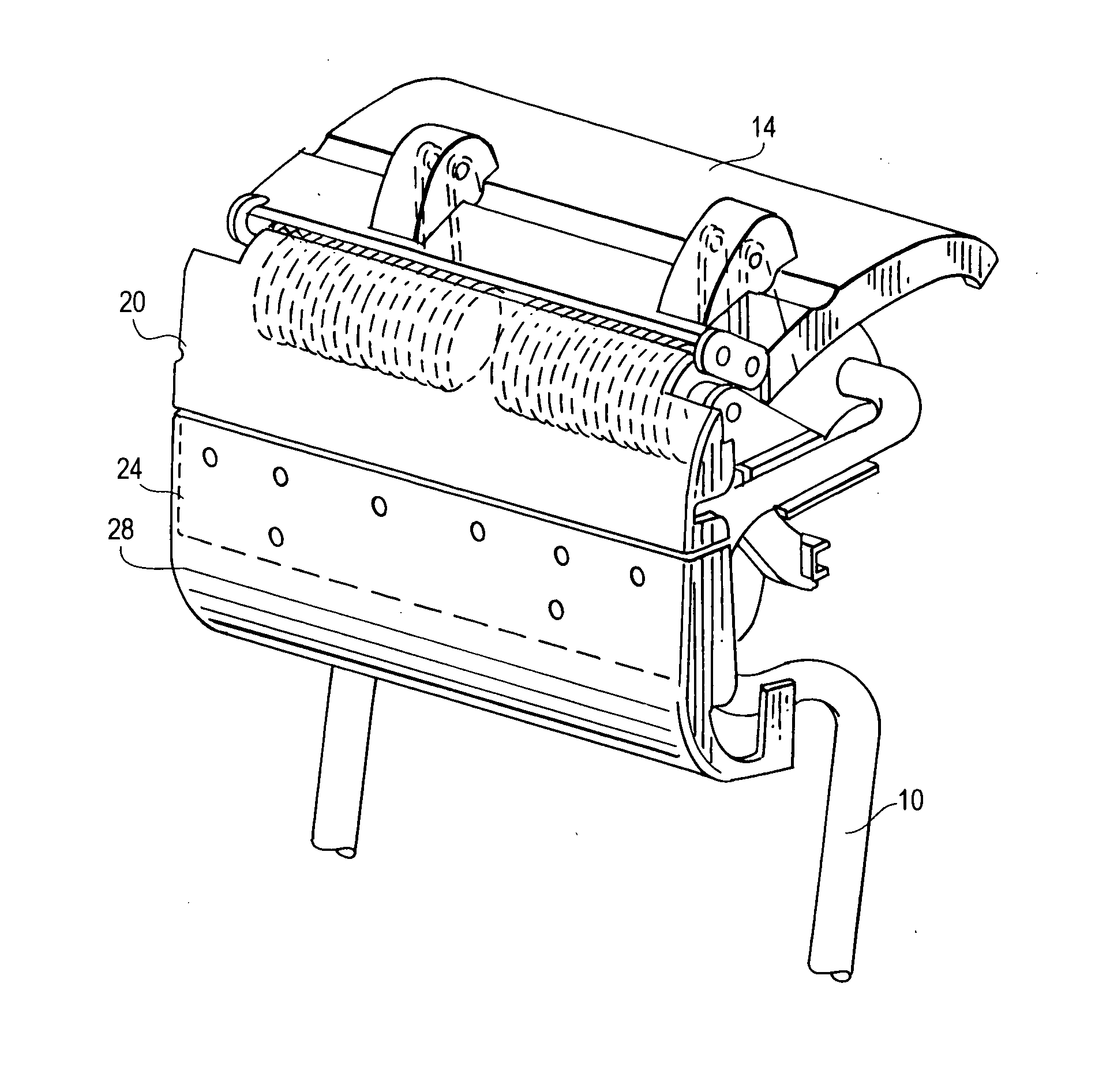
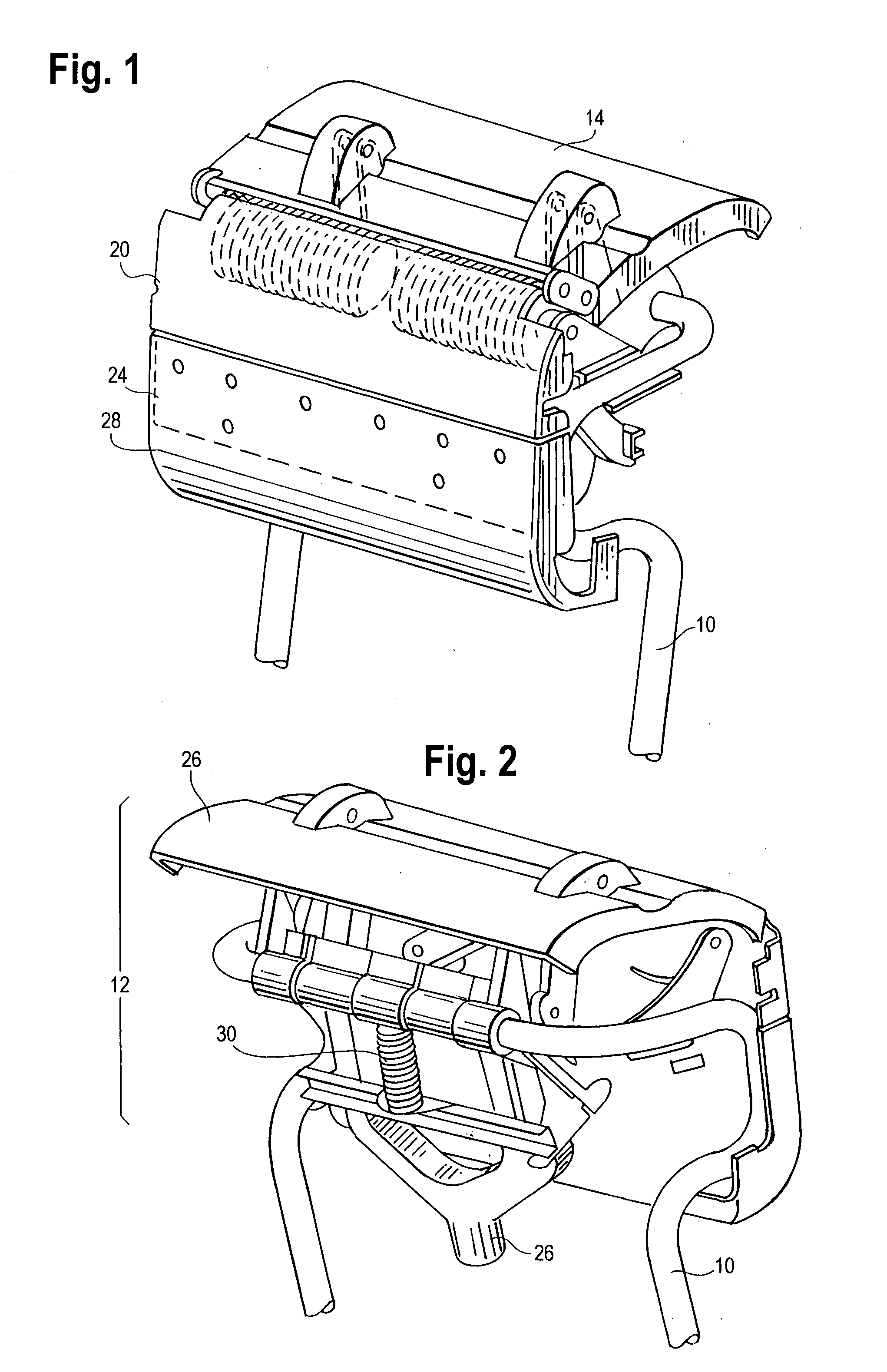
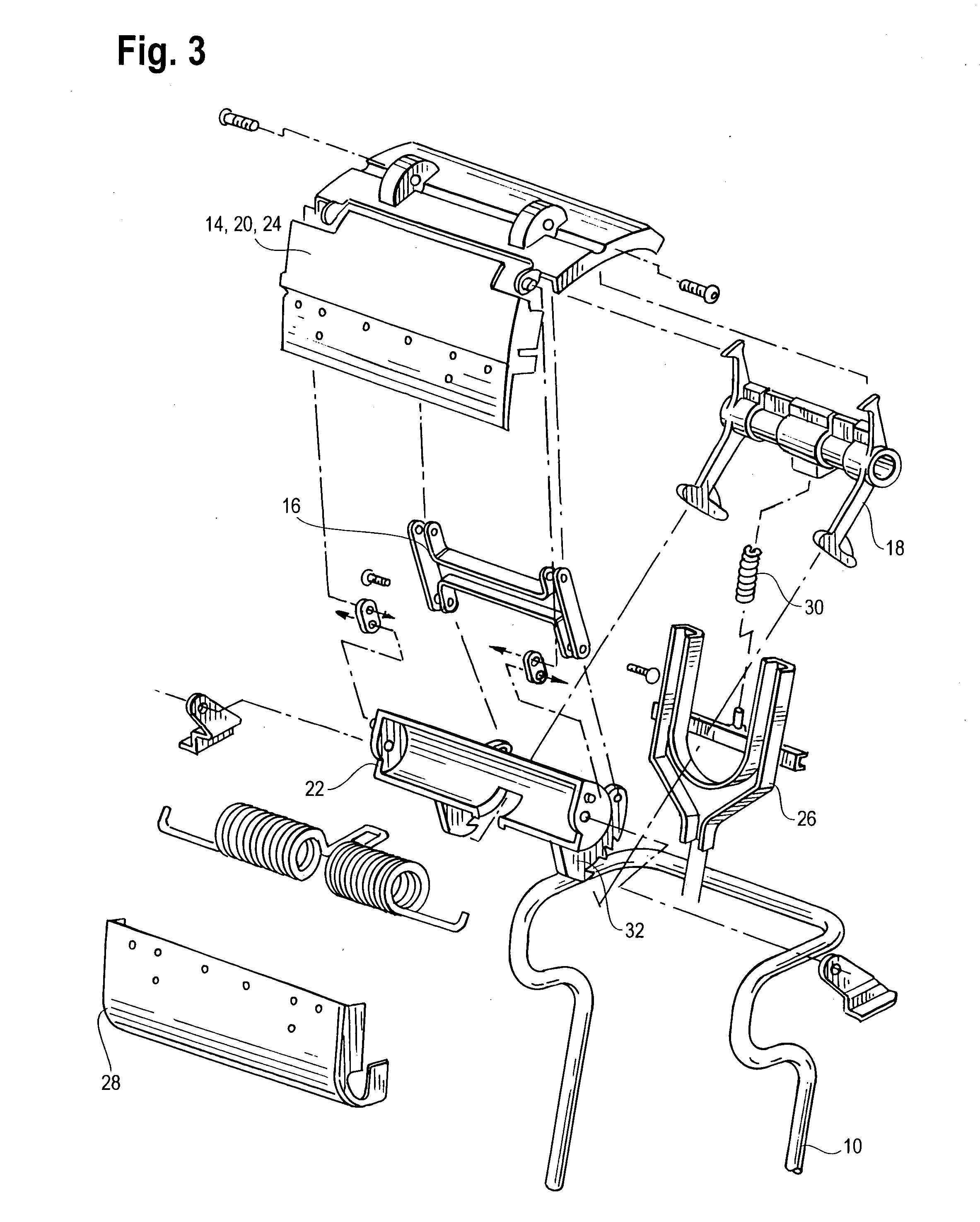
[0017] In its preferred embodiment, this active head restraint arrangement will comprise a head restraint cushion 8, at least one head restraint post 10 extending from the head restraint cushion 8 to the interior of the passenger seats, and a flip-up assembly 12 associated with the head restraint post 10 located beneath the head restraint cushion 8. This active head restraint arrangement will provide upward and forward protective motion for an occupant's head and neck while keeping the head restraint size smaller than what is typically known so as to allow users better view around the head restraint.

[0018] Referring to FIG. 2 and FIG. 4, this flip-up assembly 12 is associated with the head restraint post 10 and head restraint cushion 8. It is located underneath the head restraint cushion 8 so as to still provide an occupant the desired comfort but also affording additional protection. This flip-up assembly 12 further comprises a top flip-member 14, a push rod 16, a frame 26 attache...


PUM


Abstract

An active head restraint arrangement comprising a head restraint cushion, at least one head restraint post and head restraint post guide connecting said head restraint cushion to the interior of said passenger seats; and a flip-up assembly associated with said head restraint post beneath said head restraint cushion. Upon activation by rear impact, the flip-up assembly flips upward and forward to protect an occupant's head and neck from injury. Since this active head restraint arrangement utilizes a flip-up motion, the head restraint has a lower initial height that is dynamically increased upon activation. This feature allows the head restraint to be smaller allowing an occupant to have a better view around the head restraint.

Description

FIELD OF INVENTION [0001] This invention relates to head restraint arrangements for use in a motor vehicle. More specifically, it relates to an active head restraint arrangement. BACKGROUND OF THE INVENTION [0002] Today, most, if not all, motor vehicles come with seats equipped with head restraints. Head restraints provide not only comfort for riders but also protection for an occupant's head and neck in case of an accident. As more is learned about injuries to the head and neck, there is more of a demand to provide safer head restraints with more protection against injuries. [0003] Many head restraint arrangements in motor vehicles are stationary. They may move up or down to meet a height requirement for the occupant or there may be some pivoting movement, but often times there is little other movement. Recently, there has been a trend to provide motor vehicles with a more interactive head restraint arrangement in cases of rear impact so as to protect the occupant's head or neck mo...

Claims


Application Information

Patent Timeline
Patent Type & Authority Applications(United States)
IPC IPC(8): B60N2/48
CPCB60N2/4885B60N2/4838B60N2/888B60N2/838
Inventor YETUKURI, NAGARJUNHUMER, MLADENGREWAL, KAUR
Owner LEAR CORP
Why Eureka
Try Eureka