Water shield

Inactive Publication Date: 2005-08-25
DIXON MARK H
View PDF52 Cites 22 Cited by
  • Summary
  • Abstract
  • Description
  • Claims
  • Application Information

AI Technical Summary

Benefits of technology

[0009] The above needs are met by a water shield. The water shield comprises: a shield blank including a front surface and a back surface; at least one nozzle disposed on the front surface; a handle disposed on the back surface; and a trigger disposed proxima

Problems solved by technology

As a result, such systems are usually only good for squirting water up to ranges of about 10 feet, and the amount of water squirted by such guns was only sufficient to leave a small line of water on your friend's shirt.
Unlike

Method used


Image

  • Water shield
  • Water shield
  • Water shield

Examples


Embodiment Construction

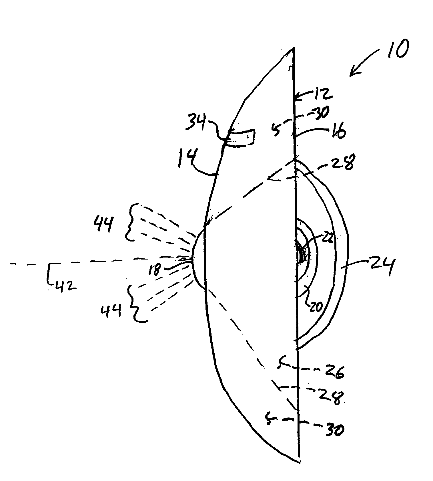
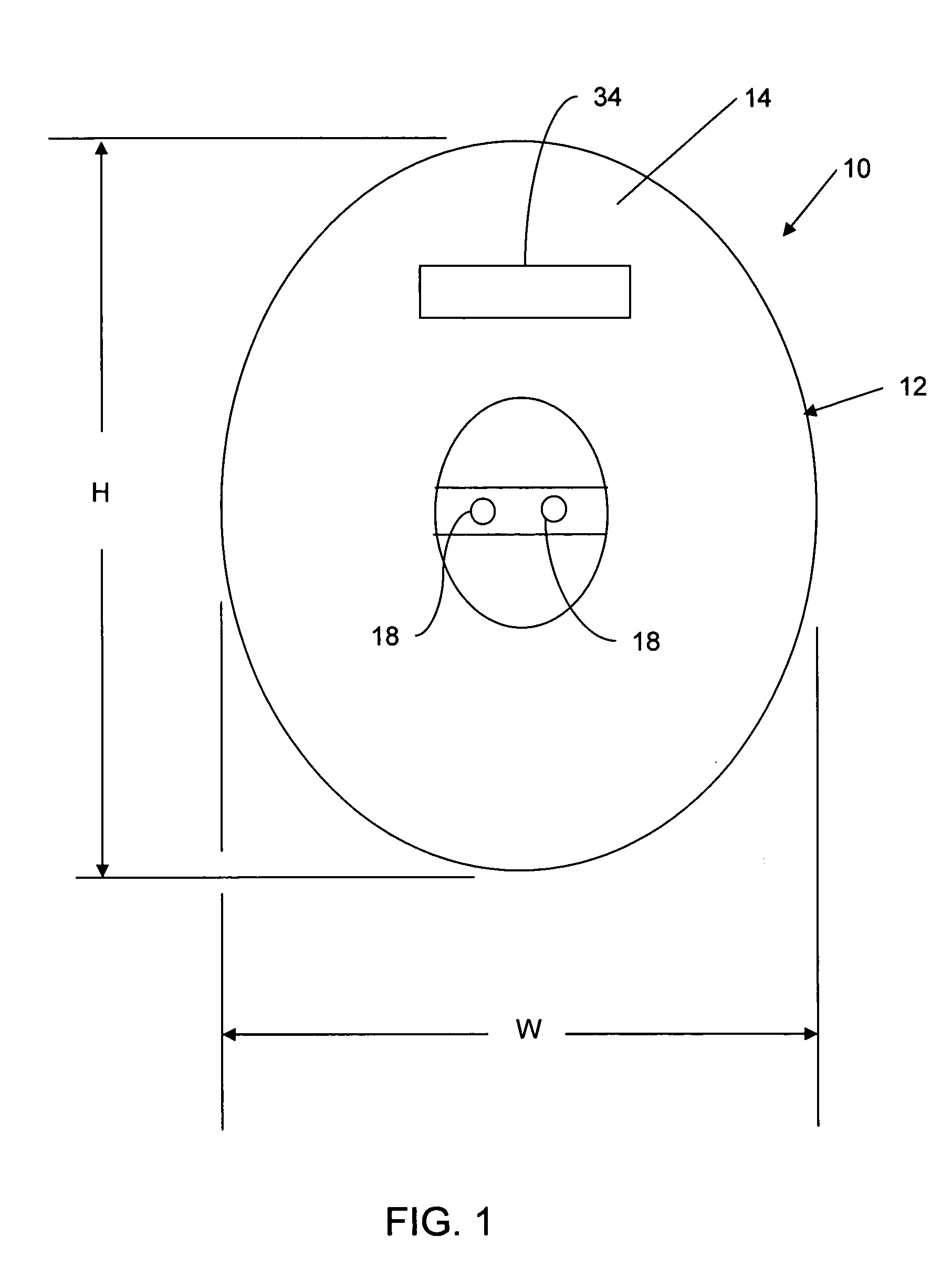
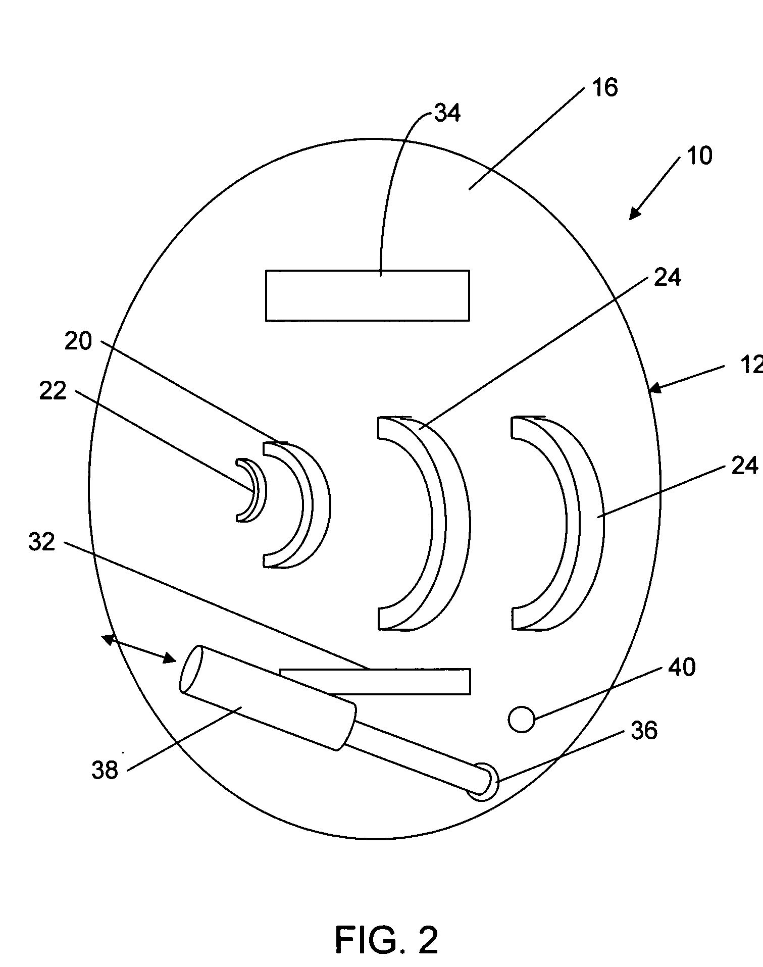
[0016] Referring to FIGS. 1-3, a water shield, shown generally at 10, includes a shield blank 12 including a front surface 14 and a back surface 16. Disposed on the front surface 14 is one or more nozzle 18, and disposed on the back surface 16 are a handle 20 and a trigger 22. The operator of the water shield 10 grabs the handle 20 to maneuver the water shield 10 in position to block any incoming streams of water from ordinary water guns. In return, the operator activates the trigger 22 to eject a stream of water from the one or more nozzle 18.

[0017] The shield blank 12 is preferably formed from a lightweight, rigid material such as, for example, molded plastic. The shield blank 12 may be shaped such that the front and back surfaces 14 and 16 are flat, or the front and back surfaces 14 and 16 may be shaped to aid in the deflection of incoming water streams. Preferably, the front surface 14 is convex. In addition to the handle 20, arm straps 24 may be added to the back surface 16 of...


PUM


Abstract

A water shield includes a shield blank including a front surface and a back surface. Disposed on the front surface is one or more nozzle, and disposed on the back surface are a handle and a trigger. The operator of the water shield grabs the handle to maneuver the water shield in position to block any incoming streams of water from ordinary water guns. In return, the operator activates the trigger to eject a stream of water from the nozzle.

Description

CROSS-REFERENCE TO RELATED APPLICATIONS [0001] This application claims the benefit of U.S. Provisional Patent Application No. 60 / 546,154 filed Feb. 20, 2004 and entitled “Water Shield”, which is incorporated by reference herein in its entirety.BACKGROUND OF THE INVENTION [0002] 1. Field of the Invention [0003] This invention is related to toys for spraying or squirting water. [0004] 2. Description of the Related Art [0005] Water guns have been popular toys for decades. Prior to the 1980's, water guns were manufactured in many different shapes and sizes. For example, some water guns were shaped as pistols (although usually made from transparent plastic), space-age “ray” guns, animals, or even cartoon characters. While the shapes and colors of the guns were quite diverse, the guns all had a very similar means of squirting water. Typically, such squirt guns used a small, spring loaded, positive displacement pumping system to force water from a reservoir in the gun through a nozzle. The...

Claims


Application Information

Patent Timeline
IPC IPC(8): B67D1/00F41B9/00
CPCF41B9/0018
Inventor DIXON, MARK H.
Owner DIXON MARK H
Why Eureka
Try Eureka