
Vehicle slide-out operating mechanism

a technology of operating mechanism and vehicle, which is applied in the field of vehicles, can solve the problems of increasing the cost and weight of the vehicle, affecting the safety of the vehicle,

Active Publication Date: 2005-08-25
LIPPERT COMPONENTS MFG INC
View PDF17 Cites 42 Cited by
  • Summary
  • Abstract
  • Description
  • Claims
  • Application Information

AI Technical Summary

Benefits of technology

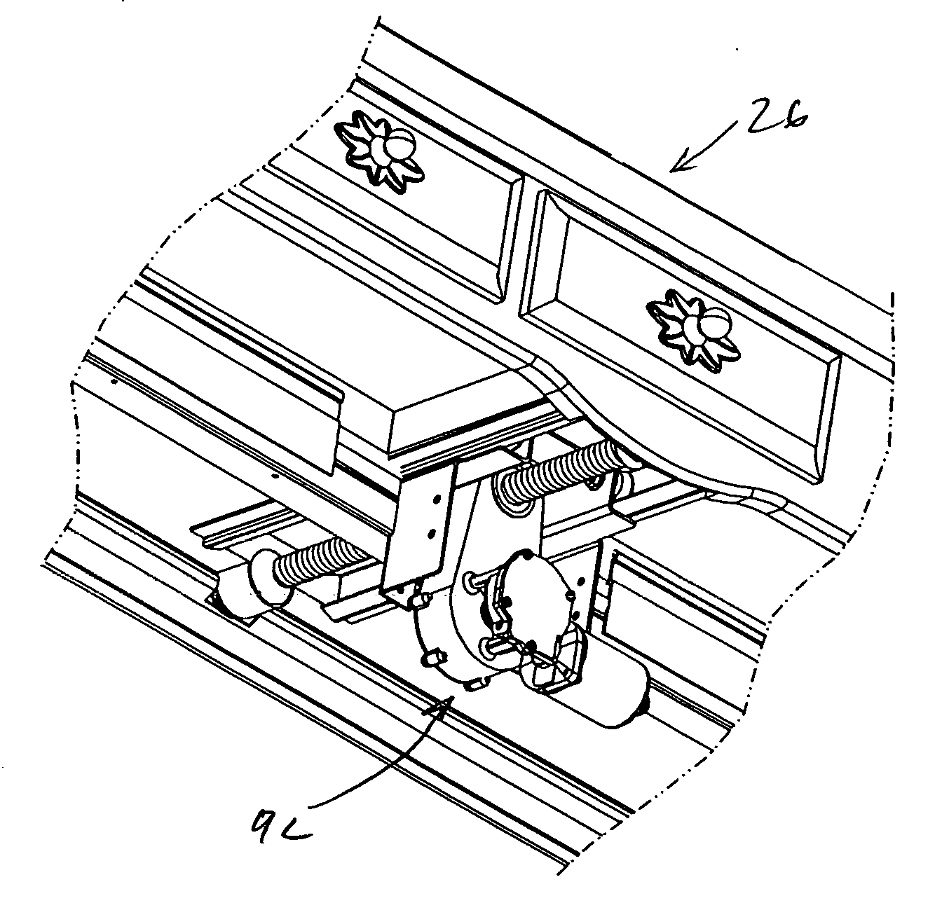
[0012] The present invention provides a vehicle with one or more slide-out sections and a compact operating mechanism for moving each slide-out section between extended and retracted positions. In the event the slide-out section is large and spans considerable width as would a living area, two or more operating mechanisms spaced apart at opposite sides of the slide-out section can be used.

Problems solved by technology

While the extendible section can increase the usable interior space of the vehicle considerably, space optimization remains an issue.
Such operating mechanisms of conventional slide-out room assemblies are large and can add significant cost and weight to a vehicle.
Another problem with vehicles having such slide-out sections is that the slide-out room may move considerably with respect to the rest of the vehicle during transit, for example, from riding over bumps, taking high-speed turns or making evasive maneuvers with the vehicle.
In extreme cases, this can result in the slide-out section actually sliding away, or extending, from the vehicle during transit.
Another problem is forming a tight seal between the slide-out section and the vehicle, particularly when the slide-out section is retracted, to keep out rain, insects and other foreign bodies.
The sliding mechanism may not be sufficient to compress the gaskets or other seals around the vehicle opening to adequately seal off the interior.
Several solutions to overcome these problems have been developed in the prior art which work to limit the amount of play in the slide-out operating mechanism, however, these are generally inadequate by themselves.

Method used


Image

  • Vehicle slide-out operating mechanism
  • Vehicle slide-out operating mechanism
  • Vehicle slide-out operating mechanism

Examples


Embodiment Construction

[0055] The present invention provides improvements to the functionality of passenger vehicles, such as a tow-along trailer or a self-propelled (motorhome) recreational vehicle, as well as other vehicles for use in construction, military, medical, education, mobile broadcast and other applications. These improvements are particularly suited for use in a vehicle having an extendable section, for example, a slide-out room or closet used to provide additional interior room space.

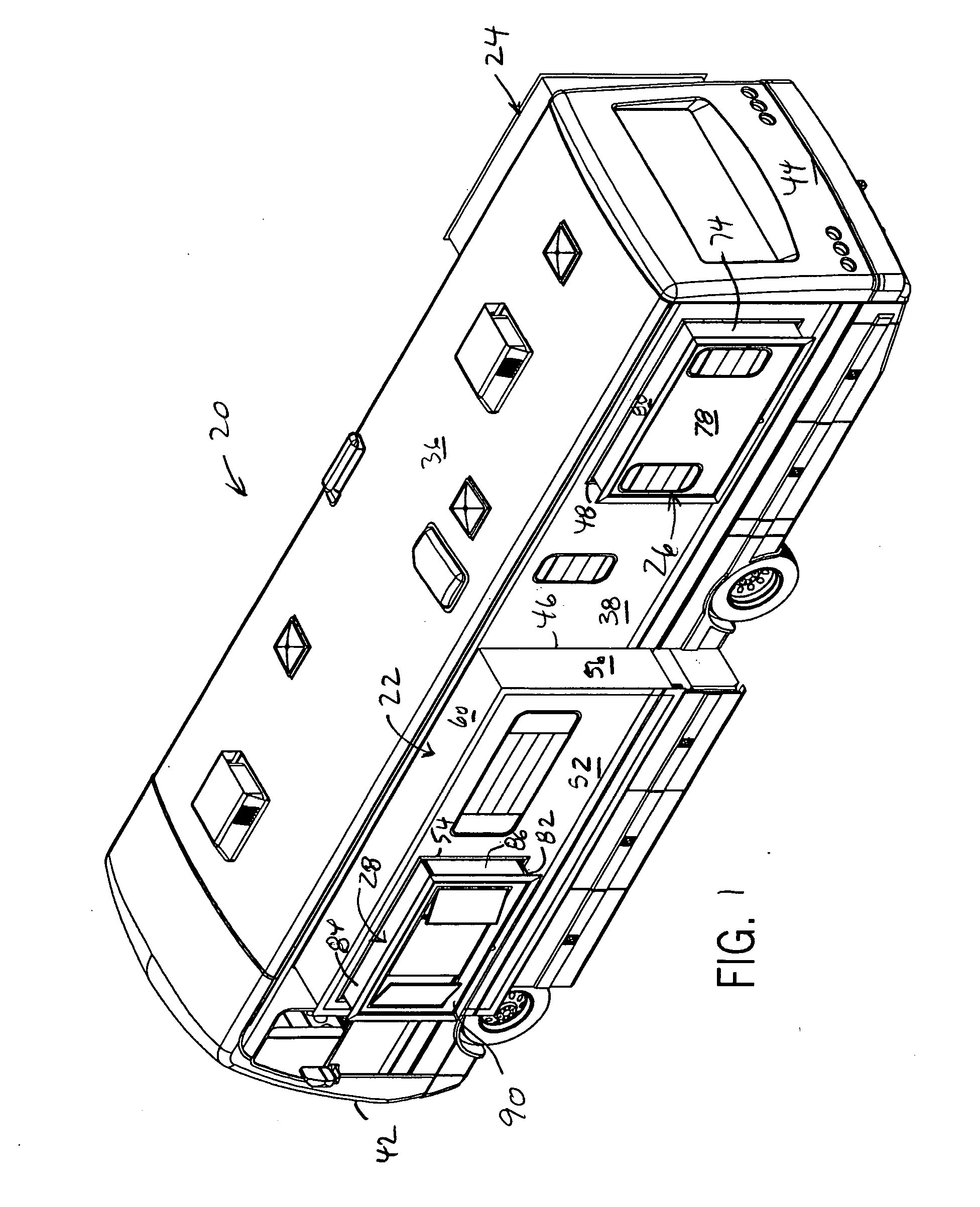
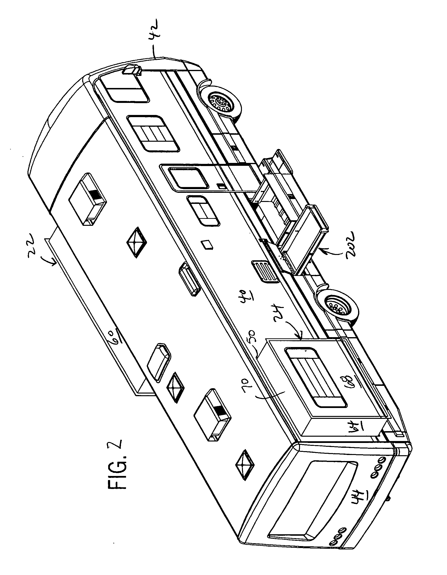
[0056] Referring now to FIGS. 1-3, a recreational vehicle 20 has a number of slide-out sections, including a slide-out room 22, a slide-out bedroom 24 and a slide-out vanity 26. Slide-out room 22 is a slide-out within a slide-out in that it has a slide-out box (or bay) window 28 that extends out from the slide-out room 22. All of the slide-out sections are slideably mounted relative to a stationary floor 30 supported by a frame 32 of the vehicle 20. The slide-out room 22 is a below the floor type in which its o...


PUM


Abstract

The invention provides a vehicle with one or more slide-out sections and a compact operating mechanism for moving each slide-out section between extended and retracted positions. In one form, the vehicle has a primary slide-out section and a secondary slide-out section mounted to extend and retract relative to the primary slide-out section. In that case, the vehicle has at least two operating mechanism, at least one for each sliding section. Each operating mechanism has two slide modules, one module is mounted the slide-out section and the other is mounted to a stationary part of the vehicle. One module includes a drive and the other includes a drive member, such as a drive screw, that interact to extend and retract the slide-out section. A track and glide arrangement can be used to facilitate relative sliding between the modules.

Description

CROSS-REFERENCE TO RELATED APPLICATION [0001] This application claims benefit to U.S. provisional application Ser. No. 60 / 546,245, filed on Feb. 20, 2004.STATEMENT OF FEDERALLY SPONSORED RESEARCH OR DEVELOPMENT [0002] Not applicable. BACKGROUND OF THE INVENTION [0003] 1. Technical Field [0004] The present invention relates to vehicles and in particular to recreational vehicles. [0005] 2. Description of the Related Art [0006] To increase the available interior space of recreational vehicles or trailers, the vehicle may have a slide-out section, such as rooms or closets. These slide-out sections usually include a floor, a roof, an end wall and one or more side walls. In the retracted position the roof, floor, and side walls are typically inside the stationary part of the vehicle, concealed from exterior view, and the end wall forms a portion of the vehicle's side wall. During transit, these sections are retracted and stored in the interior of the vehicle or trailer, with the exterior ...

Claims


Application Information

Patent Timeline
Patent Type & Authority Applications(United States)
IPC IPC(8): B60P3/34
CPCB60P3/34A47B21/0073Y10S248/92
Inventor KUNZ, JAMES R.FERGUSSON, BROCK E.
Owner LIPPERT COMPONENTS MFG INC
Learn More