Coil component and method of manufacturing the same

a technology of coils and components, applied in the field of coil components, can solve the problems of insufficient improvement difficult compacting, degradation of differential transmission characteristics, etc., and achieve the effect of high differential transmission characteristics

Active Publication Date: 2005-08-25
TDK CORPARATION
View PDF7 Cites 55 Cited by
  • Summary
  • Abstract
  • Description
  • Claims
  • Application Information

AI Technical Summary

Benefits of technology

[0030] The present invention makes it possible to manufacture a compact and low-height coil component having high differential transmission characteristics.

Problems solved by technology

However, a wire-wound coil obtained by winding a copper wire or the like around a ferrite core has a problem in that it is difficult to make compact because of structural limitations.
Since the impedance constituted by the capacitance C is inversely proportionate to a frequency, the impedance of the common mode choke coil 51 decreases, which results in degradation of differential transmission characteristics.
However, since the area over which the upper and the lower coils face each other at a minimum inter-layer distance is still relatively large in spite of the fact that the coil section has rounded corners, the differential transmission characteristics of the coils cannot be sufficiently improved.
As a result, a relatively high capacitance C is generated between the coil conductors 59 and 61, which results in a problem in that the differential transmission characteristics cannot be sufficiently improved.

Method used


Image

  • Coil component and method of manufacturing the same
  • Coil component and method of manufacturing the same
  • Coil component and method of manufacturing the same

Examples


Embodiment Construction

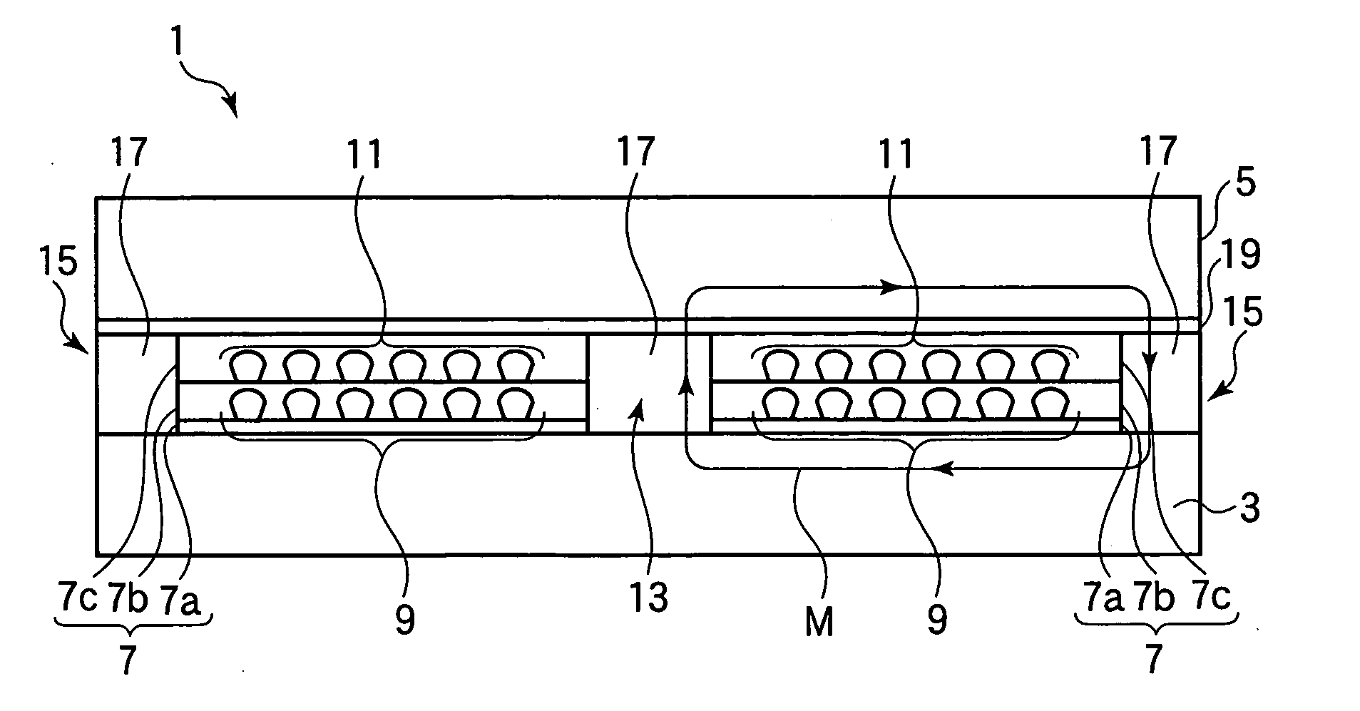
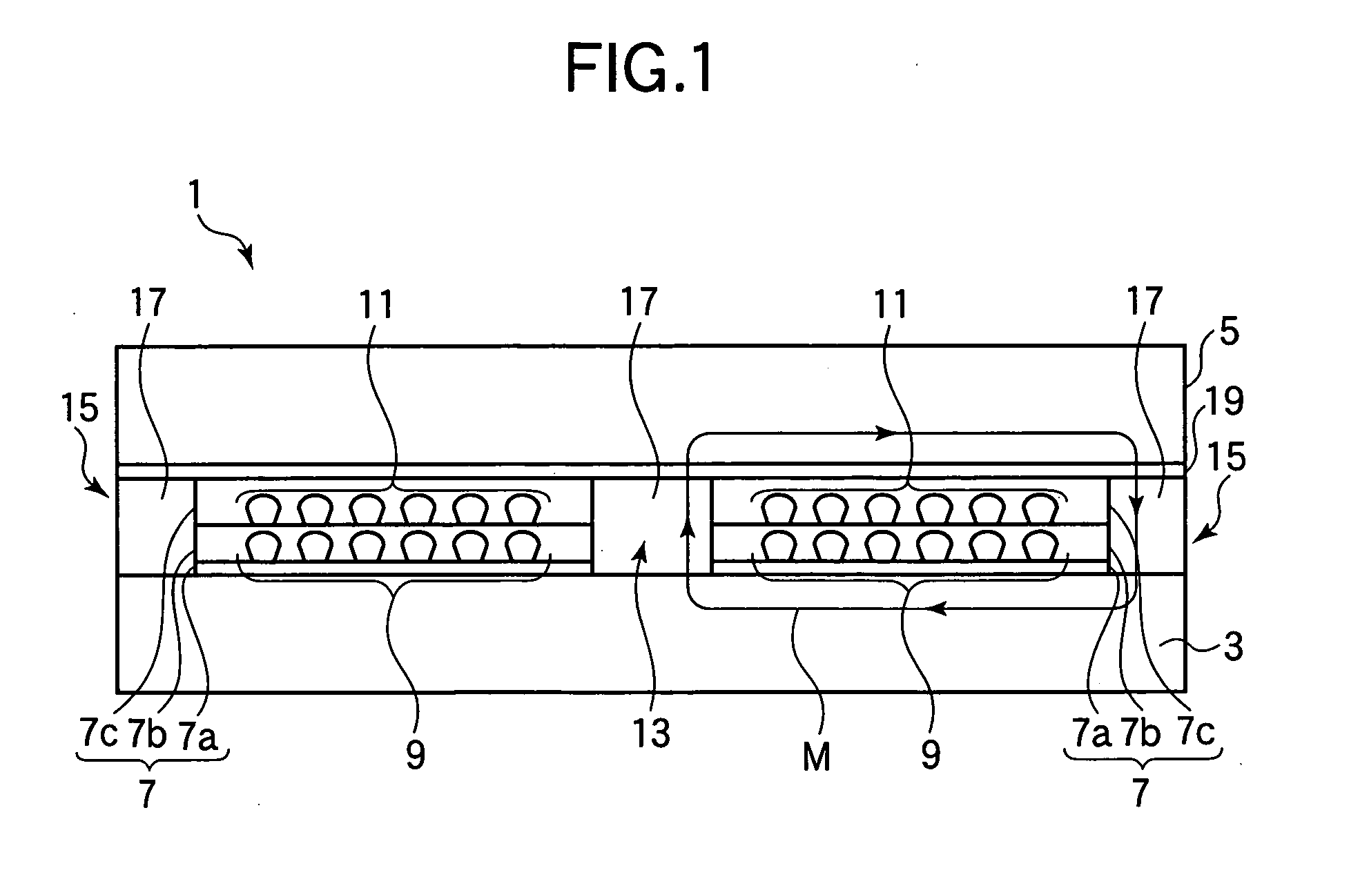
[0041] A coil component and a method of manufacturing the same according to an embodiment of the invention will now be described with reference to FIGS. 1 to 9. By way of example, the present embodiment will be described with reference to a common mode choke coil in which a common mode current that can cause electromagnetic interference is suppressed in a balanced transmission method is employed as a coil component. First, a configuration of a common mode choke coil 1 will now be described using FIG. 1. FIG. 1 shows a section of the common mode choke coil 1 taken along a plane including center axes of coil conductors 9 and 11.

[0042] As shown in FIG. 1, the common mode choke coil 1 of the present embodiment comprises an insulation film 7a formed of polyimide resin on a magnetic substrate 3 formed of ferrite, a coil conductor (first coil conductor) 9 having a spiral configuration formed of a conductive material, another insulation film 7b formed of polyimide resin, another coil condu...


PUM

PropertyMeasurementUnit
angleaaaaaaaaaa
dielectric constantaaaaaaaaaa

Abstract

The invention relates to a coil component used as a main component of a common mode choke coil or a transformer and a method of manufacturing the same, and the invention is aimed at providing a coil component with a small size and a low height having high differential transmission characteristics and a method of manufacturing the same. A common mode choke coil has a configuration in which an insulation film, a coil conductor, another insulation film, another coil conductor and another insulation film are stacked in the order listed between magnetic substrates provided opposite to each other. The coil conductors have a coil section which is in a trapezoidal general configuration. A top portion of the coil section is formed in a convex configuration such that it bulges in the form of a convex, and a bottom portion of the coil section is formed in a planar configuration.

Description

BACKGROUND OF THE INVENTION [0001] 1. Field of the Invention [0002] The present invention relates to a coil component used as a main component of a common mode choke coil or a transformer and a method of manufacturing the same. [0003] 2. Description of the Related Art [0004] Reductions in the size of electronic apparatus such as personal computers and portable phones have resulted in demand for reductions in the size and thickness (low height) of electronic components such as coils and capacitors mounted on internal circuits of electronic apparatus. [0005] However, a wire-wound coil obtained by winding a copper wire or the like around a ferrite core has a problem in that it is difficult to make compact because of structural limitations. Under the circumstance, research and development is active on chip-type coil components which can be provided with a small size and a low height. Known chip-type coil components include multi-layer type coil components provided by forming coil conduc...

Claims


Application Information

Patent Timeline
Patent Type & Authority Applications(United States)
IPC IPC(8): H01F17/00H01F27/00H01F27/34H01F30/00H01F41/04
CPCH01F17/0013H01F27/34Y10T29/4902H01F2017/0093H01F41/046
Inventor YOSHIDA, MAKOTOOKUZAWA, NOBUYUKIITO, TOMOKAZUHISHIMURA, YUKARISATO, YOSHIKAZU
Owner TDK CORPARATION
Why Eureka
Try Eureka