Walk-behind implement and handle assembly release apparatus for use with same

a technology of releasing apparatus and handle, which is applied in the field of walking behind implements, can solve the problems of excessive room, large storage footprint of mowers, and occupying wha

Inactive Publication Date: 2005-09-01
TORO CO THE
View PDF25 Cites 27 Cited by
  • Summary
  • Abstract
  • Description
  • Claims
  • Application Information

AI Technical Summary

Problems solved by technology

Thus, the mower may take up what is considered to be excessive room when not in use, i.e., when the mower is stored with the handle assembly in its conventional operating position, the mower may have a relatively large storage footprint.
While effective, some implementations of foldable handle assemblies do have drawbacks such as, for instance, requiring time consuming and / or complex manual interaction on the part of the operator to initiate folding.
Such interaction may be inconvenient, or for some operators, difficult to accomplish.
As a result, one member may potentially be displaced more than the other, resulting in only partial disengagement of the handle assembly (e.g., only one handle end) from the mower housing.

Method used


Image

  • Walk-behind implement and handle assembly release apparatus for use with same
  • Walk-behind implement and handle assembly release apparatus for use with same
  • Walk-behind implement and handle assembly release apparatus for use with same

Examples


Embodiment Construction

[0023] In the following detailed description of exemplary embodiments, reference is made to the accompanying figures of the drawing which form a part hereof, and in which are shown by way of illustration specific embodiments in which the invention may be practiced. It is to be understood that other embodiments may be utilized and structural changes may be made without departing from the scope of the present invention.

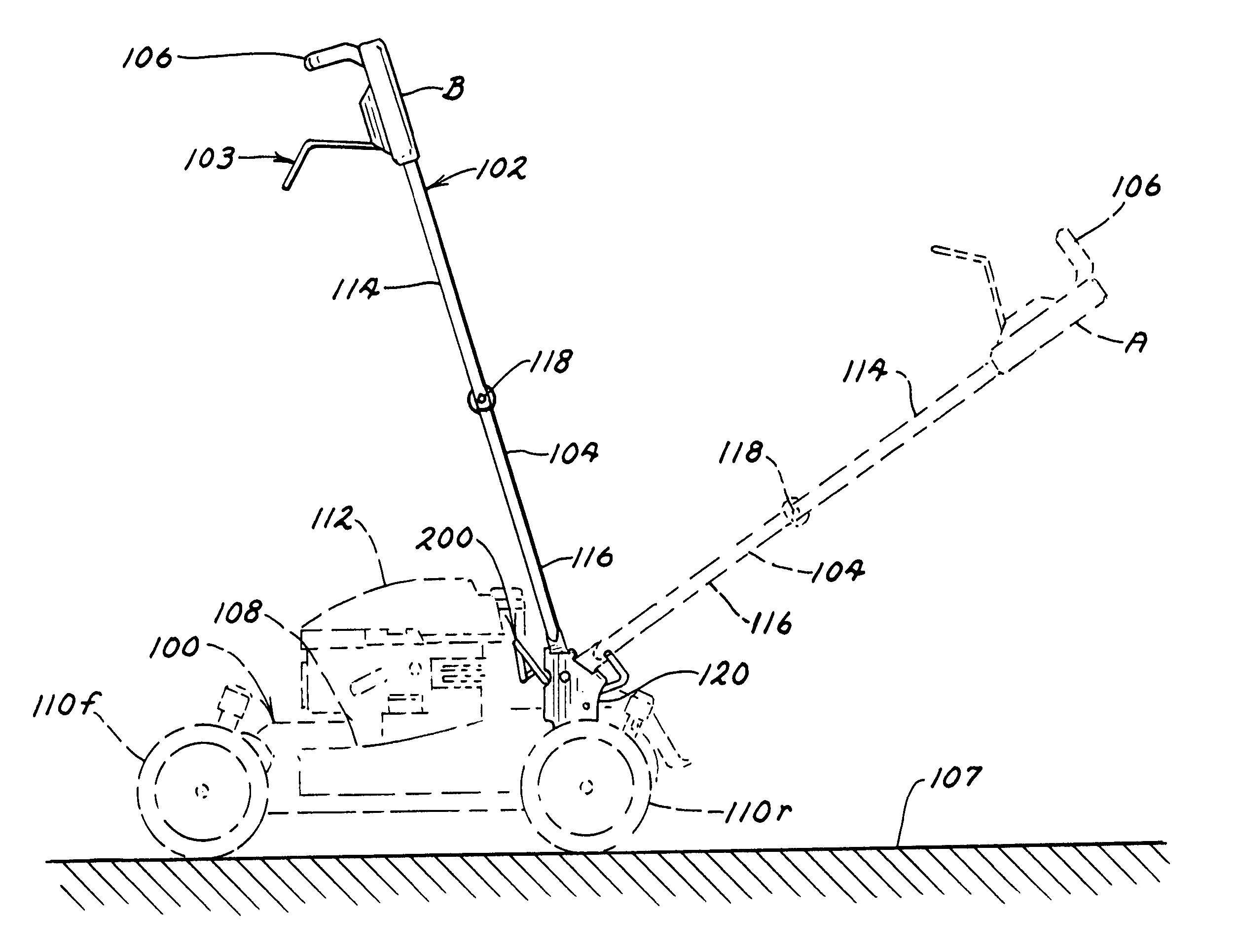
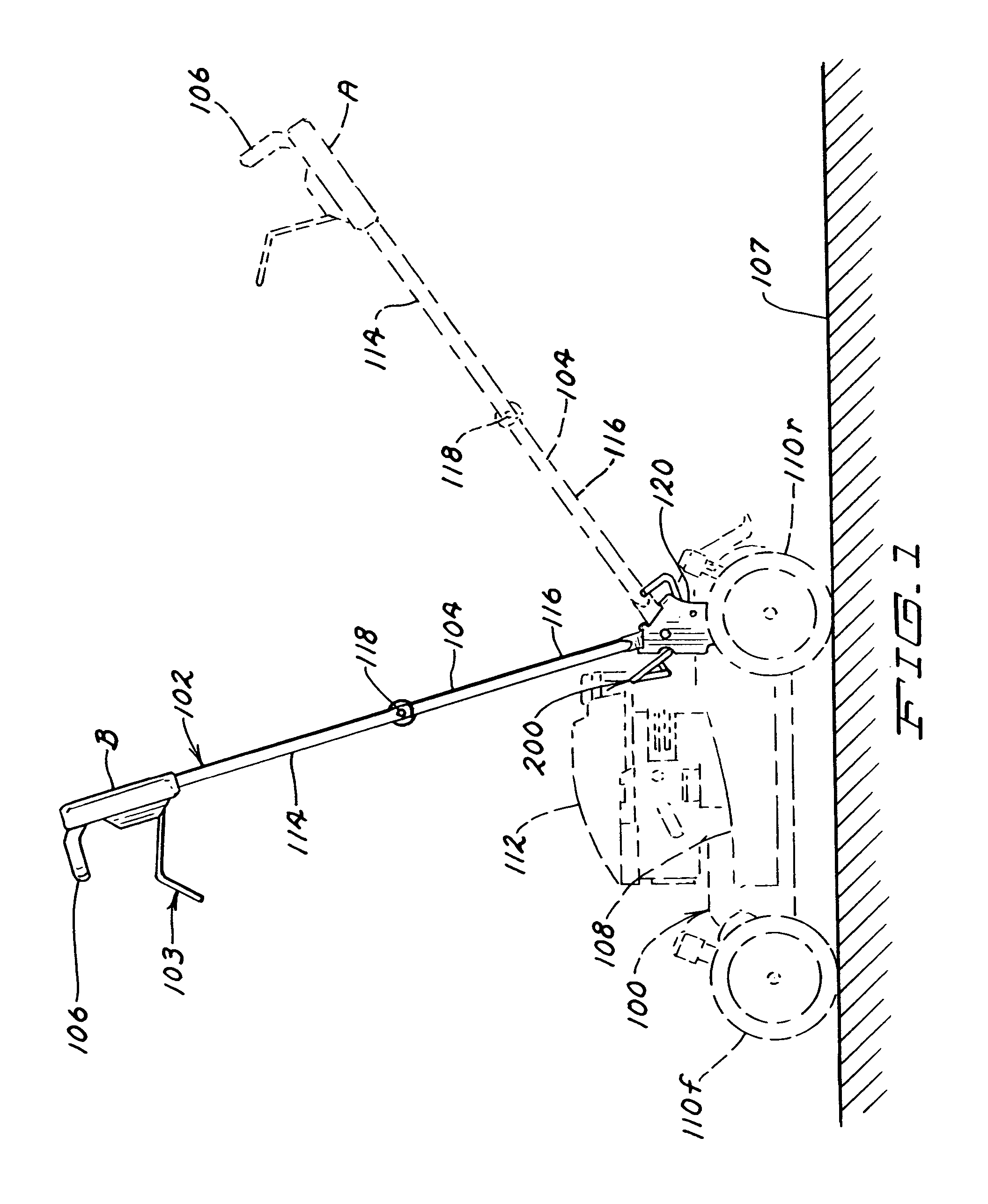
[0024] Generally speaking, the present invention is directed to apparatus and methods for permitting unlocking and movement of a handle assembly of a walk-behind implement, e.g., a rotary lawn mower, between a first operating position and at least a second storage position. As a result, the footprint of the implement may be quickly and easily reduced for storage.

[0025] While described herein in the context of a walk-behind rotary lawn mower, those of skill in the art will appreciate that the apparatus and methods of the present invention could be used with most any wa...


PUM


Abstract

A walk-behind implement, e.g., lawn mower, having a handle assembly, and a handle assembly release apparatus for use with such an implement. The release apparatus, in one embodiment, may permit unlocking of the handle assembly from a first operating position relative to a housing of the implement. Once unlocked, the handle assembly may be moved, e.g., pivoted, to a second storage position. In one embodiment, the release apparatus may include a lever member that may be actuated by the application of a force applied by an operator's foot.

Description

TECHNICAL FIELD [0001] The present invention relates to a walk-behind implement such as a lawn mower having a handle assembly and, more specifically, to a foot-actuated handle assembly release apparatus for use with the same. BACKGROUND [0002] Rotary lawn mowers are generally known in the art. Typically, such mowers include a wheeled housing forming a cutting chamber in which a rigid cutting blade rotates. A generally U-shaped handle assembly extending upwardly and rearwardly from the housing allows a walking operator to guide and manipulate the mower. The handle assembly may include two transversely spaced handle members, e.g., tubes, joined together at their respective upper ends by a cross tube forming a hand grip portion of the handle assembly. The handle assembly may be rigidly locked to the housing during operation of the mower so that the user may impart directional and control forces to the mower through the handle assembly. [0003] While effectively configured for operation,...

Claims


Application Information

Patent Timeline
Patent Type & Authority Applications(United States)
IPC IPC(8): A01D34/82
CPCY10S56/18A01D34/824
Inventor CLARKE, KHARI S.
Owner TORO CO THE
Why Eureka
Try Eureka