Adjustable exhaust assembly for pneumatic fasteners

a technology of pneumatic fasteners and exhaust assemblies, which is applied in the direction of manufacturing tools, portable drilling machines, drilling pipes, etc., can solve the problems of significantly increasing manufacturing costs, reducing performance characteristics, and reducing the overall length of the exhaust assembly, so as to increase or decrease the overall length

Inactive Publication Date: 2005-09-01
BLACK & DECKER INC
View PDF98 Cites 13 Cited by
  • Summary
  • Abstract
  • Description
  • Claims
  • Application Information

AI Technical Summary

Benefits of technology

[0011] In a further aspect, a depth adjustment system is included to permit varying the depth to which a fastener to be secured will be driven. In this aspect of the invention, a threaded thumb wheel is included to engage with a threaded portion of a pivot pin included on the intermediate linkage. A washer, biased into engagement with the thumb wheel, having a series of detents is included to secure the thumb wheel in the desired position along the pivot pin. The thumb wheel may be manipulated to increase or decrease the overall length of the contact safety system thereby varying the extent to which a fastener will be driven into a workpiece.

Problems solved by technology

Unfortunately, pneumatic fasteners may typically employ functional features for controlling and directing the air flow which involve expensive and time consuming manufacturing processes and result in decreased performance characteristics.
This may significantly increase manufacturing costs, which in turn may be passed on to the consumer.
Another problem associated with pneumatic fasteners, which employ the methods of getting the supply air to the valve piston chamber, as described above, is that these machined holes provide rough surfaces over which the air must travel.
These rough surfaces may increase air flow turbulence / friction thereby reducing the efficiency of air flow travel and possibly decreasing the efficiency of the pneumatic fastener.
These lubricants may increase the cost of operating these pneumatic fasteners and decrease productivity as the pneumatic fasteners must halt operation in order to have the lubricant provided.
This is an on-going problem as the lubricant has a limited useful lifespan and must be continuously replaced to assist in smoothing the surfaces over which the air flow must travel.
This may increase the manufacture cost.
This may cause inconvenience to an operator.

Method used


Image

  • Adjustable exhaust assembly for pneumatic fasteners
  • Adjustable exhaust assembly for pneumatic fasteners
  • Adjustable exhaust assembly for pneumatic fasteners

Examples


Embodiment Construction

[0034] Reference will now be made in detail to the presently preferred embodiments of the invention, examples of which are illustrated in the accompanying drawings.

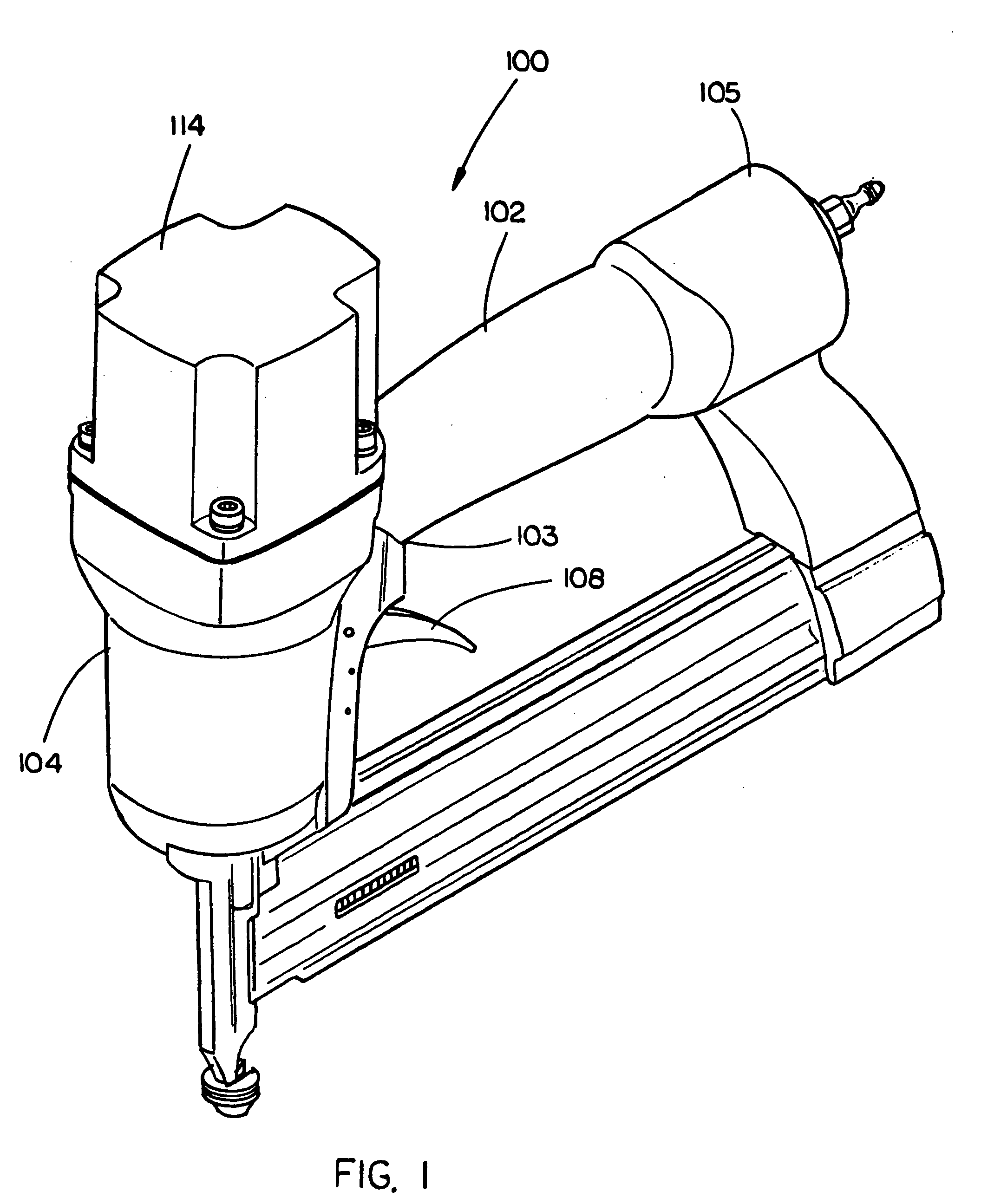
[0035] Referring now to FIG. 1, an exemplary embodiment of a pneumatic fastener 100 in accordance with the present invention is provided. In the exemplary embodiment, the pneumatic fastener 100 includes a handle 102 having a first end 103 and a second end 105. In the present embodiment, a housing 104 is coupled with the first end 103 of the handle 102. The handle 102 further includes a handle adapter 156, which enables the coupling of a compressed air supply to the pneumatic fastener 100. In addition, a trigger assembly 108 for controlling the firing of the pneumatic fastener 100 may be coupled with the handle 102, proximal to the first end 103.

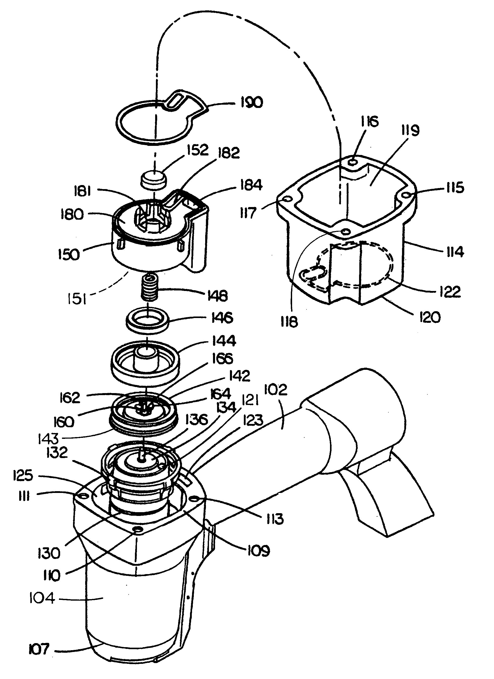
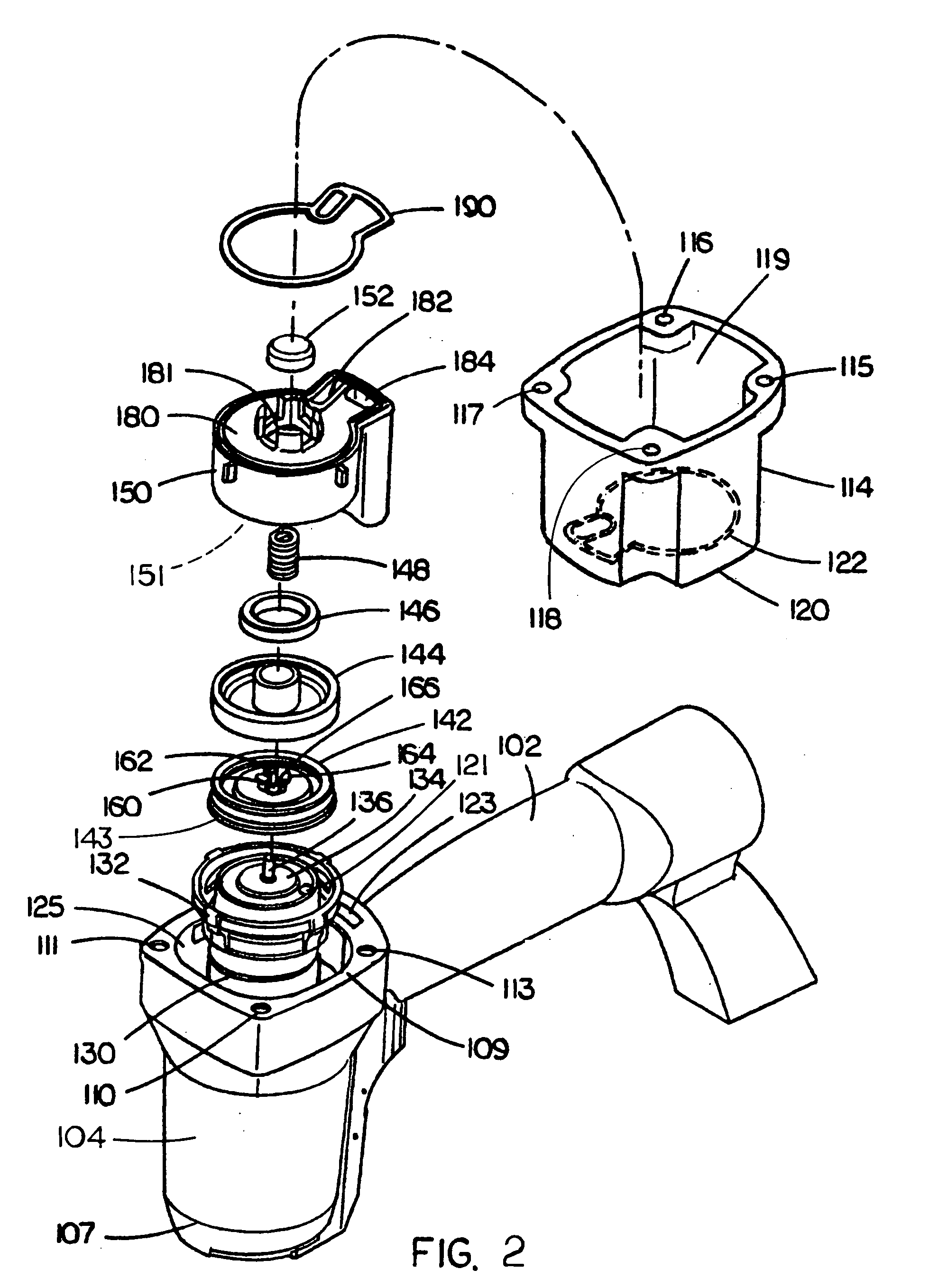
[0036] Referring now to FIG. 2, in the exemplary embodiment the housing 104 defines a housing recessed area 125 within which a piston assembly including a cylinder 130 and a pist...


PUM

PropertyMeasurementUnit
perimeteraaaaaaaaaa
forceaaaaaaaaaa
frictionaaaaaaaaaa

Abstract

An adjustable exhaust assembly for a pneumatic fastener includes a base, which includes a base plate and a protrusion protruding from the base plate. The protrusion is centrally hollow and includes an inner surface and an outer surface. The base plate includes an inlet opening and an exhaust opening defined therethrough. The inlet opening is interconnected with a channel defined by the inner surface of the protrusion. A cap is coupled to and supported by the base and includes an exit opening. A quick connector coupler is positioned inside the channel defined by the inner surface of the protrusion. When coupled to a pneumatic fastener, the quick connector coupler is suitable for connecting to an air supply hose to input compressed air to the pneumatic fastener via the channel defined by the inner surface of the protrusion and the inlet opening, and exhaust from the pneumatic fastener may exit through the exhaust opening and the exit opening.

Description

CROSS REFERENCE TO RELATED APPLICATIONS [0001] The present application claims the benefit under 35 U.S.C. § 119(e) of U.S. Provisional Patent Application Ser. No. 60 / 546,685, entitled “Oil Free Head Valve for Pneumatic Nailers and Staplers,” filed Feb. 20, 2004 which is herein incorporated by reference in its entirety.FIELD OF THE INVENTION [0002] The present invention generally relates to the field of power tools, and particularly to an adjustable exhaust assembly for pneumatic fasteners. BACKGROUND OF THE INVENTION [0003] Pneumatic power tools are commonly employed in a variety of work places to accomplish a diverse assortment of tasks. Typical pneumatic power tools include pneumatic fasteners such as pneumatic nail guns and pneumatic staple guns. These pneumatic fasteners often employ piston assemblies coupled with valve assemblies to provide the force desired to drive a fastener into a surface. It is understood that the flow of compressed air into and through these pneumatic too...

Claims


Application Information

Patent Timeline
Patent Type & Authority Applications(United States)
IPC IPC(8): B25C1/00B25C1/04B25C1/14
CPCB25C1/008B25C1/04B25C1/047B25C1/042
Inventor SCHNELL, JOHN W.WALL, DANIEL PAXTONGOODWIN, DANIEL U.ROSE, BARBARA A.
Owner BLACK & DECKER INC
Why Eureka
Try Eureka